Gehl AL550 Operators Manual Electrical and Hydraulic Diagram 50940705C
Size: 27.48 MB
Language: English
Machine: Articulated Loader
Machine Model: AL550
Part Number: 50940705C
Document: Operators Manual, Electrical and Hydraulic Diagram
Publication Date: 2022
Pages: 246 Pages
The Bookmarks of Gehl AL550 Operators Manual Electrical and Hydraulic Diagram:
Delivery Checklists
Introduction
Safety Symbol and Signal Words
Legal Notices
Contents and Use of the Operator’s Manual
Machine Orientation
Proper Machine Use
Service and Registration
Component Identification
Attachments
Vibration Information
Fire Extinguisher
Manufacturer Information
Indicator and Operation Symbols
Safety
Safety Symbol and Signal Words
Mandatory Safety Shutdown Procedure
Before Starting
During Operation
Provision for Stability/Avoiding Rollover and Tipover Accidents
Articulated Loader Stability
Applications with Load-Handling Devices
Parking the Machine
Electrical Energy
Maintenance and Service Safety Practices
Battery Hazards
Fire Hazards
Additional Safety Equipment
Crystalline Silica Exposure
Transporting the Machine
Raising the Machine with a Crane
Loading and Transporting the Machine
Safety Decals
Safety Decal Locations
ANSI-Style and Common Safety Decal Locations
ISO-Style Safety Decal Locations
Specifications
Fluids/Lubricants Types and Capacities
Payloads/Capacities
Dimensions
Weights
Coolant Compound Table
Direct and/or Indirect Visibility
Wheels/Tires
Engine
Electrical
Hydraulic System
Sound Power/Pressure Levels
Vibration Levels
Common Materials and Densities
Indicators and Controls
Display
Switches
Ignition Switch
Operator’s Seat
Joystick
Parking Brake
Horn Button
Control Lever (Option)
Throttle Controls
Travel Controls
High/Low Travel Speed Selection
Constant Speed (Option)
Differential Lock
Engine Off Lift Structure Lower
Hydraulics Transport Lock-out
Attachment Mounting
Auxiliary Hydraulic System
Hydraglide™ Switch (Option)
Cab Heat and Air Conditioning (HVAC)
Dome Light
Work Lights Switch
Beacon (Option)
Wiper/Washer and Defrost
12V Accessory Power Outlet
USB Ports (Option)
External 12V Attachment Power Connections (Option)
Battery Disconnect Switch
Operation
Operational Checks
Before Operation
Seat Belt
Starting the Engine
Machine Warm Up
Run-In Period
Stopping the Engine
Engine Stalling
Safety Interlock System (Hydraloc™)
Travel Drive Operation
Constant Speed Operation (Option)
Lift Structure Operation
Lift Structure Support
Self-Leveling and Return-To Dig
Hydraglide™ Ride Control System (Option)
Hydraulics Transport Lock-Out Operation
Connecting/Disconnecting Attachments
Powering Attachments with Hydraulic Function
Working with Buckets
Working with Pallet Forks
Diesel Particulate Filter (DPF) Regeneration Procedures
After Operation
Jump-Starting
Jump-Starting Procedure
Raising the Machine using a Crane
Towing
Loading and Transporting the Machine on a Transport Vehicle
Maintenance
Maintenance Schedule
Maintenance Interval
General Lubrication
Side Panel Removal/Replacement
Service Cover Removal/Replacement
Engine Maintenance
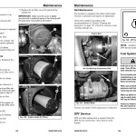
DPF Service
Fuel System Maintenance
Cooling System Maintenance
Hydraulic System Maintenance
Hydraulic Hose Maintenance
Planetary Axles
Brake Fluid Reservoir
Parking Brake Adjustment/Service
Wheels and Tires
Travel Motor Lubrication
Road Lights Adjustment
Electrical System
HVAC/Air Conditioning Maintenance
Windshield Washer Reservoir
Long-Term Storage
Final Shutdown / Decommissioning
Maintenance Log
Troubleshooting
Engine Troubleshooting
Indicator Troubleshooting
Seal and Hose Troubleshooting
Hydraulic System Troubleshooting
Hydrostatic Travel Drive System Troubleshooting
Electrical Troubleshooting
Error Codes
Schematics
Hydraulics Schematic – Standard-Flow Auxiliary
Hydraulics Schematic – High-Flow Auxiliary
Hydraulics Schematic – Standard-Flow Auxiliary with Options
Hydraulics Schematic – High-Flow Auxiliary with Options
Electrical Schematic – Rear Chassis
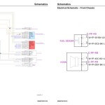
Electrical Schematic – Front Chassis
Electrical Schematic – Power Distribution
Electrical Schematic – Grounds
Electrical Schematic – Lower ROPS/FOPS
Electrical Schematic – Upper ROPS/FOPS
Electrical Schematic – Steering Column
Electrical Schematic – HVAC
Electrical Schematic – CAN Network
Electrical Schematic – Lights
Electrical Schematic – Engine (Deutz TD 2.2 L3)
Electrical Schematic — Electrical Auxiliary Circuits
Electrical Schematic — Hydraulics Electrical
EC Declaration of Conformity
Index
Torque Specifications
SAE Torque Values
#more Product: Gehl Operators Manual, Parts Catalog, Service Manual, Wiring Diagram


