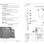
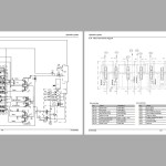
Gehl GE383Z Service Manual Electrical and Hydraulic Diagram 918197A
Size: 9.50 MB
Language: English
Machine: Compact Excavator
Machine Model: GE383Z
Part Number: 918197A
Document: Service Manual, Electrical and Hydraulic Diagram
Publication Date: 2006
Pages: 174 Pages
The Bookmarks of Gehl GE383Z Service Manual Electrical and Hydraulic Diagram 918197A:
1 Operation
1.1 General Information
1.2 Serial number location
1.3 Designated uses and exemption from liability
1.4 Abbreviations/symbols
1.5 Identification of warnings and dangers
1.6 Type decals and component numbers
1.7 Machine: overview
1.8 Cab: overview
1.9 Cab: legend
1.10 Instrument panel: overview
1.11 Instrument panel: legend
1.12 Engine compartment: overview
1.13 Chassis: overview
1.14 Tilting the cab
1.15 Cab heat/recirculated air controls
2 Specifications
2.1 Chassis
2.2 Engine
2.3 Hydraulic system
2.4 Undercarriage and swivel unit
2.5 Dozer blade
2.6 Electrical system
2.7 Noise levels
2.8 Coolant compound table
2.9 Model-specific tightening torques
2.10 General tightening torques
2.11 Dimensions
2.12 Standard Long Dipper Arm Load Diagram
2.13 Standard Long Dipper Arm with Counterweight Load Diagram
2.14 Optional Short Dipper Arm Load Diagram
2.15 Optional Short Dipper Arm with Counterweight Load Diagram
2.16 Kinematics
3 Maintenance
3.1 Fluids and lubricants
3.2 Maintenance label
3.3 Maintenance schedule
3.4 Service packages
3.5 Introduction
3.6 Fuel system
3.7 Engine lubrication system
3.8 Cooling system
3.9 Air filter
3.10 V-belt
3.11 Pressure check
3.12 Test report
3.13 Hydraulic system
3.14 Tracks
3.15 Lubrication strip
Electrical system
3.16 Cab
3.17 General maintenance
4 Engine
4.1 3TNV88-PNS engine: overview
4.2 Fuel system
4.3 Checking and adjusting valve tip clearance
4.4 Order for loosening/tightening cylinder head bolts
4.5 Checking the injection nozzles
4.6 Checking the nozzle jet
4.7 Injection time
4.8 Adjusting engine RPM
4.9 Compression
4.10 Checking the coolant thermostat
4.11 Checking the thermal switch
4.12 Oil pressure switch
4.13 Checking the coolant circuit
4.14 Engine troubleshooting
5 Hydraulic system
5.1 Hydraulic pump PVD-2B44BP-16G5-4713F
5.2 Main valve block
5.3 Drive counterbalancing system
5.4 Regeneration - dipper arm section
5.5 Bucket pre-tension
5.6 Flow rate adjustment of auxiliary hydraulics
5.7 Pilot valves
5.8 Valves
5.9 Travel drive - SN AB00855 and after (see page 5-22 for SN up to AB00854)
5.10 Travel drive - SN up to AB00854 (see page 5-19 for SN AB00854 and after)
5.11 Swivel motor
5.12 Swivel joint
5.13 Breather filter
5.14 Troubleshooting in the hydraulic system
5.15 Hydraulics diagram
5.16 Hydraulics diagram (legend)
5.17 Hydraulics diagram
5.18 Main valve block diagram
6 Electrical system
6.1 Ohm's Law (current, voltage, resistance); power
6.2 Measuring equipment and methods
6.3 Cable color coding
6.4 Relays
6.5 Electrical units
6.6 Fuse box in instrument panel
6.7 Main fuse box/relays
6.8 Relays
6.9 Socket
6.10 Tip switches on joystick
6.11 Alternator
6.12 Starter
6.13 Wiring diagram: legend
6.14 Wiring diagram
6.15 Engine wiring harness: legend
6.16 Engine wiring harness
6.17 Cab wiring harness: legend
6.18 Cab wiring harness
6.19 Roof wiring harness
7 Options
7.1 Air conditioning
7.2 Counterweight
7.3 Short dipper arm
7.4 Auxiliary hydraulics connections
7.5 Proportional controls
#more Product: Gehl Operators Manual, Parts Catalog, Service Manual, Wiring Diagram


