Gehl R135 R150 GEN2 R165 1350R 1500R NXT2 1650R Service Manual and Diagram 50940256B
Size: 257.06 MB
Language: English
Machine: Skid-Steer Loader
Machine Model:
Gehl R135 and GEN:2
Gehl R150 and GEN:2
Gehl R165
Mustang 1350R and NXT2
Mustang 1500R and NXT2
Mustang 1650R
Part Number: 50940256B
Document: Service Manual, Electrical and Hydraulic Diagram
Publication Date: 2020
Pages: 366 Pages
The Bookmarks of Gehl R135 R150 GEN2 R165 1350R 1500R NXT2 1650R Service Manual and Diagram 50940256B:
Introduction
Safety Symbol and Signal Words
Contents and Use of this Manual
Machine Orientation
Proper Machine Use
Service and Registration
Fields of Application
Using Attachments
Vibration Information
Fire Extinguisher Location
Manufacturer Information
Indicator and Operation Symbols
Safety
Safety Symbol and Signal Words
Mandatory Safety Shutdown Procedure
Safety Reminders
Crystalline Silica Exposure
Safety Decals
Safety Equipment
Guards and Shields
Operator’s Position
Safety Interlock System (Hydraloc™)
Parking Brake
ROPS/FOPS
Rear Window Emergency Exit
Lift Arm Support
Battery Disconnect Switch (Option)
Indicators and Controls
Control Keypad
Accessory Keypad Indicators/Buttons
Optional Lights/Lockout Keypad Indicators/Buttons
Information Center Electronic Display
Controls
Two-Speed Drive (Option)
Lift Arm Float
Hydraglide™ Ride Control System
Beacon/Position/Work Lights
HVAC (Optional)
Windshield Wiper/Washer
Dome Light
Accessory Plug
Battery Disconnect Switch (Option)
Attachment Mounting
Auxiliary Hydraulic System
Operation
Before Starting the Engine
Starting the Engine
Run-In Period
Stopping the Machine
Engine Stalling
Parking the Machine
Brake Release Operation (Option)
Jump-starting
Travel Drive Operation
Transport on Public Roads
Lift Arm Operation
Changing Attachments
Self-Leveling (Option)
Using Buckets
Using Pallet Forks
Loading and Transporting the Machine on a Transport Vehicle
Towing
Lifting the Machine Using a Crane or Hoist
Diesel Particulate Filter (DPF) Regeneration Procedures (DPF Models)
Maintenance
Maintenance Schedules
Maintenance Log
General Lubrication
Removing Foreign Material
Tilting the ROPS/FOPS
Lifting the Machine
Engine Maintenance
Fuel System Maintenance
Engine Air Cleaner
DPF Service (DPF Models)
V-Belt Maintenance
Cooling System
Hydraulic System
Cab Heater Filter Replacement
Hydraulic Hose Maintenance
Chaincases
Seat and Restraint Bar Switches
Bucket Cutting Edge
Wheel Nuts
Tires
Electrical System
Windshield Washer Reservoir
Long-Term Storage
Final Shutdown / Decommissioning
Hydrostatic System
Introduction
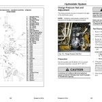
Charge Pressure Test and Adjustment
Hydrostatic Pump Relief Valves
Hydrostatic Pump Removal and Installation
Hydrostatic Pump Drive Coupling Removal and Installation
Drive System
Introduction
Drive Chain Adjustment
Axle Housing Assembly Removal and Installation
Axle and Wheel Bearing Disassembly/Assembly
Drive Chain Removal and Installation
Controls
Drive System Mechanical Control Linkage
Neutral Centering
Control Handle Position Adjustment
Control Linkage Tracking Adjustment
Hydraulic System
Introduction
General Hydraulic Service Notes
Pressure Test and Adjustment
Tilt Cylinder Test
Self-Leveling Valve Test
Self-Leveling Valve Adjustment
Lift Cylinder Test
Solenoid Valve Test
Solenoid Valve Disassembly/ Reassembly
Hydraglide™ Ride Control Solenoid Test
Hydraulic Cylinder Disassembly/ Assembly
Main Control Valve
Electrical System
Power Distribution
Start/Glow Solenoid Test
Control Modules
J1939 Data Connector
Electrically-Controlled Standard Auxiliary Hydraulics Troubleshooting
Electronic Throttle Test
Main Control Unit LEDs/Pins Description
Controller Area Network (CAN) Functional Detail
Work Light Bulb Replacement
Dome Light Bulb Replacement
Battery Removal/Installation
Lift Arms and ROPS/FOPS
Lift Arm Bushing Replacement
Lift Arm Stop Installation and Adjustment
R150/1500R, R165/1650R Lift Cylinder Removal/Installation
R135/1350R Lift Cylinder Removal/Installation
R150/1500R, R165/1650R ROPS/ FOPS Removal/Installation
R135/1350R ROPS/FOPS Removal/Installation
ROPS/FOPS Rear Window Removal and Installation
Models R165/1650R Tier 4 Engine Removal/Installation
Model R165/1650R Engine Removal
Model R165/1650R Engine Installation
Models R135/1350R/R150/1500R Tier 4 Engine Removal/Installation
Models R135/1350R/R150/1500R Engine Removal
Models R135/1350R/R150/1500R Engine Installation
Troubleshooting
Engine Troubleshooting
Indicator Lamp Troubleshooting
Seal and Hose Troubleshooting
Hydraulic System Troubleshooting
Hydrostatic Drive System Troubleshooting
Electrical Troubleshooting
Error Codes
Hydraulic Schematic – Models 135R/1350R
Hydraulic Schematic – Models 135R/1350R with Power-A-Tach and Self-Level
Hydraulic Schematic – Models 150R/1500R
Hydraulic Schematic – Models 150R/1500R with Power-A-Tach, Hydraglide and Self-Level
Hydraulic Schematic – Models 165R/1650R with T-Bar or Hand/Foot Controls (Single-Speed)
Hydraulic Schematic – Models 165R/1650R with T-Bar or Hand/Foot Controls (Single-Speed) with Power-A-Tach, Hydraglide and Self-Level
Hydraulic Schematic – Models 165R/1650R with T-Bar or Hand/Foot Controls (Two-Speed)
Hydraulic Schematic – Models 165R/1650R with T-Bar or Hand/Foot Controls (Two-Speed) with Power-A-Tach, Hydraglide and Self-Level
Hydraulic Schematic – Models 165R/1650R with Joystick Controls (Single-Speed)
Hydraulic Schematic – Models 165R/1650R with Joystick Controls (Single-Speed) with Power-A-Tach, Hydraglide and Self-Level
Hydraulic Schematic – Models 165R/1650R with Joystick Controls (Two-Speed)
Hydraulic Schematic – Models 165R/1650R with Joystick Controls (Two-Speed) with Power-A-Tach, Hydraglide and Self-Level
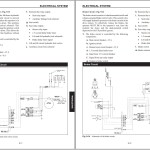
Electrical Schematic – Chassis (Page 1 of 2)
Electrical Schematic – ROPS (Page 1 of 3)
Electrical Schematic – ROPS (Page 2 of 3)
Electrical Schematic – ROPS (Page 3 of 3)
Electrical Schematic – Engine (Tier 4)
Electrical Schematic – Model R165 Engine (Interim Tier 4)
Electrical Schematic – Models R135/R150 Engine (Interim Tier 4)
Specifications
Fluid Capacities/Lubricants
Weights
Payloads/Capacities
Engine
Coolant Compound Mixtures
Hydraulics
Travel Speeds
Electrical System
Sound Levels
Vibration Levels
Dimensions
Features
Common Materials and Densities
Index
Torque Specifications
#more Product: Gehl Operators Manual, Parts Catalog, Service Manual, Wiring Diagram


