Gehl RT175 RT210 RT250 RT175 RT210 Gen2 RT175 RT210 RT250 Gen3 Service Manual and Diagram 50940164C
Size: 19.98 MB
Language: English
Machine: Compact Track Loader
Machine Model: RT175 RT210 RT250 RT175 RT210 Gen2 RT175 RT210 RT250 Gen3
Part Number: 50940164C
Document: Service Manual, Electrical and Hydraulic Diagram
Publication Date: 2018
Pages: 440 Pages
The Bookmarks of Gehl RT175 RT210 RT250 RT175 RT210 Gen2 RT175 RT210 RT250 Gen3 Service and Diagram 50940164C:
Introduction
Safety Symbol
Contents and Use of this Manual
Safety Symbol and Signal Words
Machine Orientation
Proper Machine Use
Service and Registration
ROPS/FOPS Certification Label
Component Identification
Fields of Application
Using Attachments
Vibration Information
Fire Extinguisher
Manufacturer Information
Indicator and Operation Symbols
Safety
Safety Symbol and Signal Words
Mandatory Safety Shutdown Procedure
Before Starting
During Operation
Applications with Load-Handling Devices
Parking the Machine
Electrical Energy
Maintenance and Service Safety Practices
Battery Hazards
Fire Hazards
Additional Safety Equipment
Crystalline Silica Exposure
Transporting the Machine
Lifting the Machine with a Crane
Loading and Transporting the Machine
Safety Decals
ANSI-Style Safety Decals
ISO-Style Safety Decals
Specifications
Fluids/Lubricants Types and Capacities
Dimensions
Payloads/Capacities
Weights
Track Drive
Coolant Compound Table
Engine
Hydraulic System
Electrical System
Sound Power/Pressure Levels
Vibration Levels
Features
Standard Features
Optional Features
Common Materials and Densities
Controls
Multi-Function Display
Switches/Indicators
Multi-Function Display Screens
Control Joysticks
Straight Tracking Adjust
Parking Brake/Work Hydraulics Lock-out
Cab Heat and Air Conditioning (Option)
Operator’s Seat
Seat Belt
Armrest/Joystick Console Adjustment
Throttle Controls
Travel Controls
Travel Speed Range Selection
Lift Arm Float Button
Hydraglide™ Button (Option)
Work Lights
Battery Disconnect Switch (Option)
Windshield Wipers/Washer
Operation
Operational Checks
Before Operation
Starting the Engine
Warm Up
Run-In Period
Stopping the Engine
Engine Stalling
Diesel Particulate Filter (DPF) Regeneration Procedures
After Operation
Jump-Starting
Travel Drive Operation
Lift Arm Operation
Self-Leveling
Lift Arm Float
Hydraglide™ Ride Control System (Option)
Hydraulics Control Lock
Lift Arm Support
Connecting/Disconnecting Attachments
Powering Attachments with Hydraulic Function
Optional 14-Pin Connector
Lifting the Machine using a Crane
Loading and Transporting the Machine on a Transport Vehicle
Storage Box
Maintenance
Maintenance Schedule
Maintenance Interval
Engine Maintenance
DPF Service
Fuel System Maintenance
Hydraulic System Maintenance
Hydraulic Hose Maintenance
Travel Motor Maintenance
Track Maintenance
General Lubrication
Tilting ROPS/FOPS
Electrical System
Long-Term Storage
Air Conditioning Maintenance
Windshield Washer Reservoir
Final Shutdown / Decommissioning
Maintenance Log
Lift Arm and ROPS/FOPS
Lift Arm Alignment Stops
Tilt Stop Adjustment
Lift Arm Removal
Lift Arm Installation
ROPS/FOPS Service
ROPS/FOPS Removal
ROPS/FOPS Installation
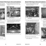
Model RT250 Engine Removal/ Installation
Engine Removal – Model RT250
Engine Installation – Model RT250
Models RT175/RT210 Tier 4 Engine Removal/Installation
Tier 4 Engine Removal Model RT175 (S/N 811001 and Up) Model RT210 (S/N 921001 and Up)
Tier 4 Engine Installation Model RT175 (S/N 811000 and Up) Model RT210 (S/N 921000 and Up)
RT175/RT210 interim Tier 4 Engine Removal/Installation
Interim Tier 4 Engine Removal Model RT175 (S/N 811000 and Before) Model RT210 (S/N 921000 and Before)
Interim Tier 4 Engine Installation Model RT175 (S/N 811000 and Before) Model RT210 (S/N 921000 and Before)
Hydraulic Equipment
General Hydraulic Service Notes
Hydraulic Oil Analysis
Hydraulic Control Valve
Hydraulic Pilot Valve
Self-Level Valve
Float/Hydraglide™ Valve
Travel Drive Motors
Hydrostatic Drive Pump
Hydrostatic Pump Swash Plates
Hydrostatic Pump Removal
Hydrostatic Pump Installation
Hydrostatic Pump Drive Coupling Removal and Installation
Hydrostatic Pump Input Shaft Seal Replacement
Hydraulic Gear Pump
Hydraulic Cylinder Disassembly/ Assembly
Hydraulic System Tests
Hydrostatic Pumps
Hydrostatic Drive System Pressures
Hydrostatic Charge Pressure Test and Adjustment
Main Relief Pressure Test
Main Pressure Adjustment
Tilt/Lift Cylinder Relief Pressure Tests
Cylinder Drift Tests
Cylinder Internal Leakage Tests
Electrical/Control Systems
Electrical Schematics
Battery
Power Distribution
Electrical Control System
CAN System Service/Computer Connection
Lighting
Electronics Diagnostic Kit
Diagnostic Kit Operation
Displayed Telemetry Information
Troubleshooting
Engine Troubleshooting
Indicator Lamp Troubleshooting
Seal and Hose Troubleshooting
Hydraulic System Troubleshooting
Hydrostatic Travel Drive System Troubleshooting
Hydrostatic Drive Motors Troubleshooting
Electrical Troubleshooting
Miscellaneous Troubleshooting
Error Codes
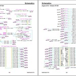
Schematics
Schematic Conventions
Model RT250 (SN 70501 and Up) Schematics
Model RT175 (Serial Numbers 811001 and Up) Model RT210 (Serial Numbers 921001 and Up)
Model RT175 with Tier 4 Engines (Serial Numbers 411051 and Up) Model RT210 with Tier 4 Engines (Serial Numbers 921651 and Up)
Model RT175 with interim Tier 4 Engines (Serial Numbers 811000 and Before) Model RT210 with interim Tier 4 Engines (Serial Numbers 921000 and Before)
Hydraulic Schematic
Index
#more Product: Gehl Operators Manual, Parts Catalog, Service Manual, Wiring Diagram


