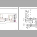
Gehl VT320 Mustang 3200VT Service Manual Electrical and Hydraulic Diagram 50940548E
Size: 49.78 MB
Language: English
Machine: Track Loader
Machine Model: Gehl VT320, Mustang 3200VT
Part Number: 50940548E
Document: Service Manual, Electrical and Hydraulic Diagram
Publication Date: 2021
Pages: 368 Pages
The Bookmarks of Gehl VT320 Mustang 3200VT Service Manual Electrical and Hydraulic Diagram 50940548E:
Table of Contents
Safety
Safety Symbol and Signal Words
Mandatory Safety Shutdown Procedure
Before Starting
During Operation
Applications with Load-Handling Devices
Parking the Machine
Electrical Energy
Maintenance and Service Safety Practices
Battery Hazards
Fire Hazards
Additional Safety Equipment
Crystalline Silica Exposure
Transporting the Machine
Lifting the Machine with a Crane
Loading and Transporting the Machine
Safety Decals
ANSI-Style Safety Decals
Lifting the Machine using a Crane
Loading and Transporting the Machine on a Transport Vehicle
Introduction
Contents and Use of this Manual
Machine Orientation
Component Identification
Machine Model and Serial Number Locations
ROPS/FOPS Certification Label
Indicator and Operation Symbols
Machine Controls and Operation
Maintenance
Maintenance Schedule
Engine Maintenance
Diesel Exhaust Fluid (DEF) Service
Fuel System Maintenance
Hydraulic System Maintenance
Hydraulic Hose Maintenance
Travel Motor Maintenance
Track Maintenance
General Lubrication
Tilting ROPS/FOPS
Electrical System
Long-Term Storage
Air Conditioning Maintenance
Windshield Washer Reservoir
Final Shutdown / Decommissioning
Engine
General Information
Engine Access
Deutz SerDia Connection/Software
Engine Maintenance
Engine Cooling System
Engine Removal/Installation
Diesel Exhaust Fluid (DEF) Service
Fuel System Maintenance
Engine Troubleshooting
Cooling System
General Information
Radiator/Coolers Removal
Radiator/Coolers Installation
Hydrostatic Drive System
General Information
General Hydraulic Service Notes
Hydraulic Oil Analysis
Hydrostatic Drive Pump
Hydrostatic Pump Relief Valves
Travel Drive Troubleshooting
Neutral Centering Check/Adjustment
Straight Tracking Adjustment
Hydrostatic Pump Removal and Installation
Hydrostatic Pump Drive Coupling Removal and Installation
Travel Motors
Travel Drive High-Speed Troubleshooting
Tracks
Parking (SAHR) Brake Malfunctions
Hydrostatic Drive System Troubleshooting
Work Hydraulics
General Information
General Hydraulic Service Notes
Hydraulic Oil Analysis
Main Pressure Test and Adjustment
Hydraulic Gear Pump
Control Valve
Tilt/Lift Cylinder Circuits Components
Tilt/Lift Cylinder Service/Tests
Hydraulic Cylinder Disassembly/ Assembly
Work Hydraulics Tests and Solenoid Valves
Hydraglide
Solenoid Valve Disassembly/ Reassembly
Work Hydraulics Troubleshooting
Hydraulic Schematic
(Gehl SN 0040301 and Up; Mustang SN 0060301 and Up; All Manitou)
Hydraulic Schematic - (Gehl SN 0040300 and Before; Mustang SN 0060300 and Before)
Electrical Control System
Electrical Control System General Information
Control Modules
CAN System Service/Computer Connection
Operation/Controller Area Network (CAN) Functional Organization
Accessories and Options Functional Detail
CAN/Control System Troubleshooting
Indicator Lamp Troubleshooting
Electrical System
Batteries
Power Distribution
Glow Relay Solenoid Test
Power-A-Tach Relay Solenoid Test
Control Modules
Lighting
Wire Harness Diagrams
Chassis Wire Harness Diagram - (Gehl SN 0040301 and Up; Mustang SN 0060301 and Up; all Manitou)
Chassis Wire Harness Diagram - (Gehl SN 0040300 and Before; Mustang SN 0060300 and Before)
Engine Wire Harness Diagram - (Gehl SN 0040301 and Up; Mustang SN 0060301 and Up; all Manitou)
Engine Wire Harness Diagram - (Gehl SN 0040300 and Before; Mustang SN 0060300 and Before)
ROPS/FOPS (Cab) Wire Harness Diagram - (Gehl SN 0040301 and Up; Mustang SN 0060301 and Up; all Manitou)
ROPS/FOPS (Cab) Wire Harness Diagram - (Gehl SN 0040300 and Before; Mustang SN 0060300 and Before)
Operator’s Seat Wire Harness Diagram - (Later Machines)
Operator’s Seat Wire Harness Diagram - (Early Machines)
Electrical Schematics
Chassis - (Gehl SN 0040301 and Up; Mustang SN 0060301 and Up; all Manitou)
Electrical Schematic – Chassis - (Gehl SN 0040300 and Before; Mustang SN 0060300 and Before)
Electrical Schematic – Engine - (Gehl SN 0040301 and Up; Mustang SN 0060301 and Up; all Manitou)
Electrical Schematic – Engine - (Gehl SN 0040300 and Before; Mustang SN 0060300 and Before)
Electrical Schematic – Rear Door
Electrical Schematic – ROPS/FOPS (Cab)
Electrical Schematic – Seat
Electrical Schematic – Road Lights
Electrical Schematic – 14-Pin Connector
Lift Arm
Lift Arm Support
Lift Arm Alignment Stops
Tilt Stop Adjustment
Lift Arm Removal
Lift Arm Installation
ROPS/FOPS/Cab
Tilting ROPS/FOPS
ROPS/FOPS Removal
ROPS/FOPS Installation
HVAC System
Air Conditioning Refrigerant Recovery
Air Conditioning System Charging
Specifications
Fluids/Lubricants Types and Capacities
Dimensions
Payloads/Capacities
Weights
Track Drive
Coolant Compound Table
Engine
Hydraulic System
Electrical System
Sound Power/Pressure Levels
Features
Standard Features
Optional Features
Common Materials and Densities
Index
Torque Specifications
#more Product: Gehl Operators Manual, Parts Catalog, Service Manual, Wiring Diagram


