

John Deere 670G 670GP 672G 672GP Repair Manual TM14072X19 2022


Support Contact:
Admin@autoepcsoft.org
John Deere 670G 670GP 672G 672GP Repair Manual TM14072X19 2022
Data Size: 39.51 MB
File Type: PDF
Language: English
Manufacturer: John Deere
Applicable Machine: Motor Graders
Document: Repair Manual
Machine Model: John Deere 670G ; 670GP ; 672G ; 672GP Motor Graders
PIN: 1DW670GX_ _F678818—680877
Serial Number: F678818-680877
Book Number: TM14072X19
Publication Date: 2022
Page: 503 Pages
List Contents:
Introduction
Manual Identification—READ THIS FIRST!
Contents
General Information
Safety
Information for European Union Directives and Eurasian Economic Union Technical Regulations Compliance
To the Customer
Sound and Vibration Specifications
Recognize Safety Information
Follow Safety Instructions
Operate Only If Qualified
Wear Protective Equipment
Avoid Unauthorized Machine Modifications
Inspect Machine
Stay Clear of Moving Parts
Avoid High-Pressure Fluids
Avoid High-Pressure Oils
Work In Ventilated Area
Avoid Static Electricity Risk When Refueling
High Debris Applications
Prevent Fires
In Case of Machine Fire
Prevent Battery Explosions
Handle Chemical Products Safely
Handle Starting Fluid Safely
Decommissioning — Proper Recycling and Disposal of Fluids and Components
Exhaust Filter Ash Handling and Disposal
Prepare for Emergencies
Clean Debris from Machine
Use Steps and Handholds Correctly
Start Only From Operator′s Seat
Use and Maintain Seat Belt
Prevent Unintended Machine Movement
Avoid Work Site Hazards
Keep Riders Off Machine
Avoid Backover Accidents
Avoid Machine Tip Over and Machine Damage
Operating or Traveling On Public Roads
Inspect and Maintain ROPS
Travel Safely
Prevent Acid Burns
Add and Operate Attachments Safely
Park and Prepare for Service Safely
Service Machines Safely
Clean Exhaust Filter Safely
Service Cooling System Safely
Remove Paint Before Welding or Heating
Make Welding Repairs Safely
Drive Metal Pins Safely
Service Tires Safely
Use Proper Lifting Equipment
Torque Values
Metric Bolt and Cap Screw Torque Values
Additional Metric Cap Screw Torque Values
Unified Inch Bolt and Cap Screw Torque Values
Service Recommendations for 37° Flare and 30° Cone Seat Connectors
Service Recommendations for O-Ring Boss Fittings
Straight Fitting
Angle Fitting
Service Recommendations for Flared Connections—Straight or Tapered Threads
Service Recommendations for Flat Face O-Ring Seal Fittings
O-Ring Face Seal Fittings With SAE Inch Hex Nut and Stud End for High-Pressure Service Recommendations
O-Ring Face Seal Fittings With Metric Hex Nut and Stud End for Standard Pressure Service Recommendations
O-Ring Face Seal Fittings With Metric Hex Nut and Stud End for High-Pressure Service Recommendations
Service Recommendations for Metric Series Four Bolt Flange Fitting
Service Recommendations For Inch Series Four Bolt Flange Fittings
Inch Series Four Bolt Flange Fitting for High-Pressure Service Recommendations
Service Recommendations For Non-Restricted Banjo (Adjustable) Fittings
Service Recommendations For O-Ring Boss Fittings With Shoulder
Metric 24° O-Ring Seal DIN 20078 Service Recommendations
Wheels
Powered Wheels and Fasteners
Wheel Remove and Install
Tire Remove and Install
Axles and Suspension Systems
Input Drive Shafts and U-Joints
Transmission-to-Rear Axle Drive Shaft Remove and Install
Transmission-to-Rear Axle Drive Shaft Disassemble and Assemble
Non-Powered Wheel Axles
Front Wheel Hub and Spindle Remove and Install—Non 6WD
Front Wheel Hub and Spindle Disassemble and Assemble—Non 6WD
Front Axle Remove and Install—Non 6WD
Powered Wheel Axles
Front Wheel Hub and Spindle Remove and Install—6WD
Front Wheel Hub and Spindle Disassemble and Assemble—6WD
Front Wheel Hub and Spindle Disassemble and Assemble With Steering Angle Sensor—6WD
6WD Drive Hub Disassemble and Assemble
Planetary Drive Disassemble and Assemble
Planetary Brake Disassemble and Assemble
6WD Bearings Remove and Install
6WD O-Ring Metal Face Seal Remove and Install
Front Axle Remove and Install—6WD
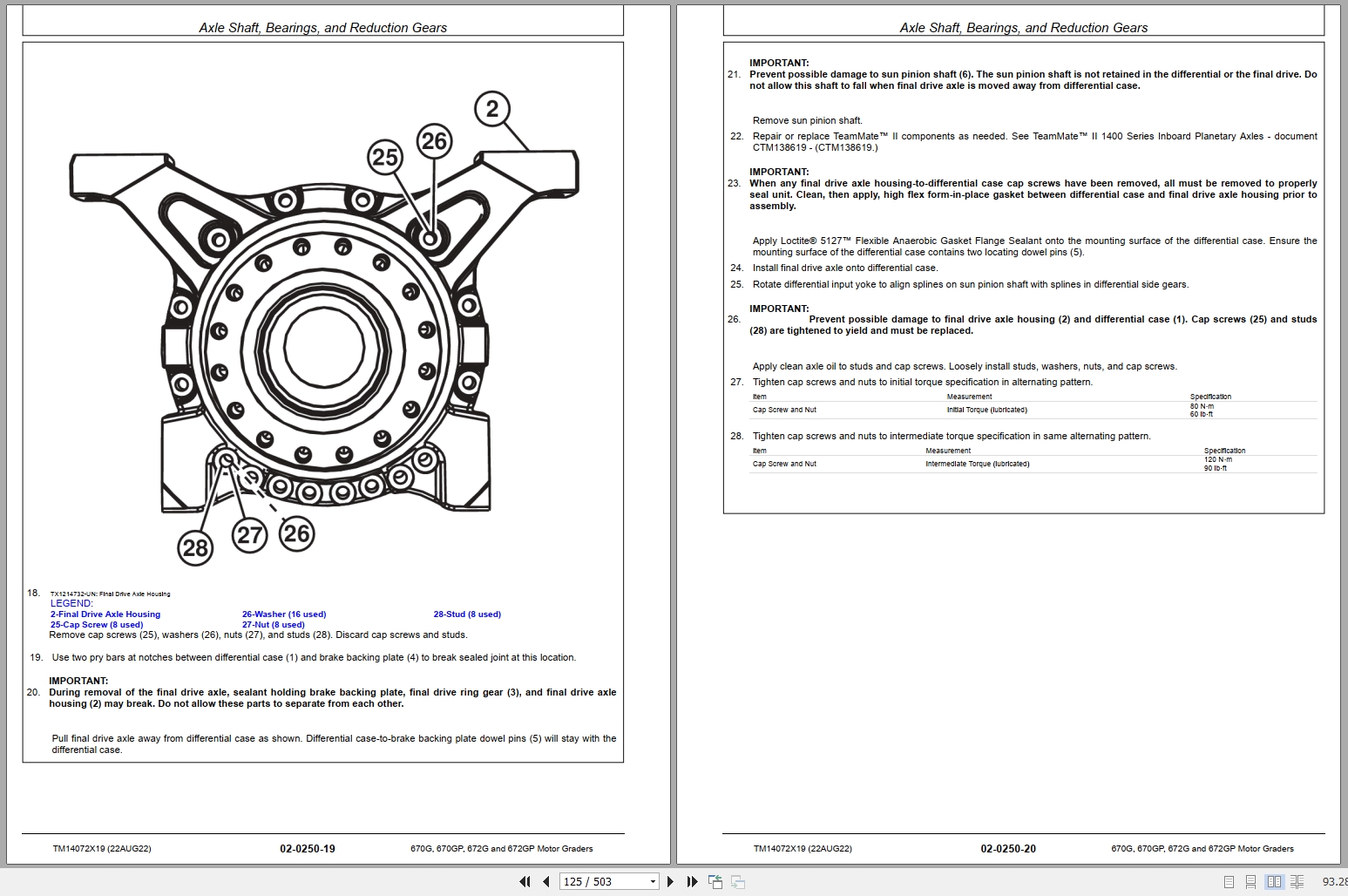
Axle Shaft, Bearings, and Reduction Gears
TeamMate™ II 1400 Series Inboard Planetary Axle—Use CTM138619
Rear Axle Remove and Install
Tandem and Wheel Axle Assembly Remove and Install
Tandem Wheel Axle Assembly Remove and Install
Tandem Wheel Axle Assembly Disassemble and Assemble
Tandem Pivot Disassemble and Assemble
Final Drive Axle Remove and Install
Tandem Drive Shaft Remove and Install
Drive Chain Remove and Install
Hydraulic System
Six-Wheel Drive (6WD) Pump Remove and Install
MACHINE PREPARATION
REMOVAL
INSTALLATION
6WD Pump Disassemble and Assemble
DISASSEMBLE
ASSEMBLE
6WD Charge Pump Remove and Install
6WD Engagement Manifold Remove and Install
Differential Lock Pump Remove and Install
6WD Motor Remove and Install
6WD Motor Disassemble and Assemble
Transmission
Removal and Installation
Transmission Remove and Install
DF180 Transmission
Hydraulic System
Transmission Charge Pump Remove and Install
Engine
Removal and Installation
John Deere Engine
Engine Remove and Install
REMOVAL
INSTALLATION
Flywheel Housing Remove and Install
Engine Auxiliary System
Cooling System
Fan Blade Remove and Install
MACHINE PREPARATION
REMOVAL
INSTALLATION
Radiator Remove and Install
Machine Preparation
Hydraulic Oil Cooler Remove and Install
REMOVAL
INSTALLATION
Transmission and Differential Oil Cooler Remove and Install
Machine Preparation
Fuel Cooler Remove and Install
REMOVAL
INSTALLATION
Charge Air Cooler Remove and Install
REMOVAL
INSTALLATION
External Exhaust System
Exhaust Tube Remove and Install
Removal
Installation
Diesel Oxidation Catalyst (DOC) Remove and Install
Machine Preparation
Removal
Installation
Diesel Particulate Filter (DPF) Remove and Install
Machine Preparation
Removal
Installation
Outlet Cone Remove and Install
Machine Preparation
Removal
Installation
Exhaust Filter Structure Remove and Install
REMOVAL
INSTALLATION
Service Filter Cleaning
Selective Catalyst Reduction (SCR) Remove and Install
Torque Specifications
Weight Specifications
Machine Preparation
Additional Information
Diesel Exhaust Fluid (DEF) Tank Remove and Install
Diesel Exhaust Fluid (DEF) Tank Header Remove and Install
MACHINE PREPARATION
REMOVAL AND INSTALLATION
Diesel Exhaust Fluid (DEF) Tank Header Disassemble and Assemble
Diesel Exhaust Fluid (DEF) Baffle Remove and Install
Diesel Exhaust Fluid (DEF) Tank Header Suction Filter Remove and Install
Diesel Exhaust Fluid (DEF) Tank Cleaning Procedure
Cleaning Procedure—DEF Tank Removed
Cleaning Procedure—DEF Tank Installed
Diesel Exhaust Fluid (DEF) Dosing Unit Remove and Install
Removal
Installation
Coolant Control Valve Remove and Install
MACHINE PREPARATION
REMOVAL
INSTALLATION
Diesel Exhaust Fluid (DEF) Dosing Injector Remove and Install
Diesel Exhaust Fluid (DEF) Decomposition Tube Remove and Install
External Fuel Supply Systems
Fuel Tank Remove and Install
Fast Fill Fuel System Disassemble and Assemble—If Equipped
DISASSEMBLE
Additional Information
ASSEMBLE
Torsional Isolator
Elements
Torsional Isolator Remove and Install
Steering System
Power Steering
Toe-In Check and Adjustment
Hydraulic System
Steering Wheel, Column, and Valve Remove and Install—Standard Controls
Steering Wheel, Column, and Valve Remove and Install—EH Controls
EH Controls Steering Canceling Valve Remove and Install
Steering Valve Disassemble and Assemble
Steering Cylinder Remove and Install
Hydraulic Cylinder Disassemble and Assemble
Wheel Lean Cylinder Remove and Install
Secondary Steering Accumulator Remove and Install—If Equipped
Service Brakes
Active Elements
Service Brake Repair
Hydraulic System
Service Brake Valve Remove and Install
Service Brake Bleeding
Brake Accumulator Remove and Install
Park Brake
Active Elements
Park Brake Repair
Electrical System
Removal and Installation
Controller Remove and Install
Auxiliary Valve Controller (AVC)
Engine Control Unit (ECU)
Vehicle Control Unit (VCU)
Hydraulic Valve Controller (HVC)
Transmission Control Unit (TCU)
Steering Angle Sensor Remove and Install
MACHINE PREPARATION
REMOVAL
INSTALLATION
Replace Weather Pack™ Connector
Install Weather Pack™ Contact
Replace DEUTSCH® Connectors
Replace DEUTSCH® Rectangular or Triangular Connectors
Install DEUTSCH® Contact
Replace (Pull Type) Metri-Pack™ Connectors
Replace (Push Type) Metri-Pack™ Connectors
Replace Connectors
Install INCH Contact
Repair 32 and 48 Way CINCH® Connectors
Frame or Supporting Structure
Frame Installation
Welding On Machine
Welding Repair of Major Structure
Separate Frames at Articulation Joint
Articulation Bearing Replacement
Rear Platform Remove and Install
Operator`s Station
Removal and Installation
Cab Remove and Install
Cab Remove and Install—GP Machine Only
Operator Enclosure
Windowpanes Remove and Install
REMOVAL
INSTALLATION
Cab Door Handle Remove and Install
Cab Door Latch Remove and Install
Rivet Nut Installation
Remove Rivet Nut
Install Rivet Nut
Wiper Arm Installation
Front Wiper Arm Installation
Lower Front Wiper Arm Installation
Rear Wiper Arm Installation
Pedal Assembly
Inching Pedal Remove and Install
Steering Tilt Console
Steering Support Console Remove and Install—Standard Controls
Steering Support Console Remove and Install—EH Controls
Console Tilt Remove and Install
Steering Tilt Assembly Remove and Install
Seat and Seat Belt
Seat Remove and Install
Seat Belt Remove and Install
Armrest Remove and Install
Armrest Remove and Install—EH Controls
Armrest Disassemble and Assemble—EH Controls
Standard Seat Disassemble and Assemble
Deluxe Seat Disassemble and Assemble
Air Suspension Disassemble and Assemble
Heating and Air Conditioning
R134a Refrigerant Cautions and Proper Handling
Flush and Purge Air Conditioning System
Procedure Set-Up
Evaporator Flush and Purge
Procedure Wrap-Up
R134a Refrigerant Oil Information
R134a Refrigerant Recovery, Recycling, and Charging Station Installation Procedure
Recover R134a Refrigerant
Evacuate R134a System
Charge R134a System
Expansion Valve Remove and Install
Freeze Control Switch Remove and Install
Heater Control Valve Remove and Install
Blower Motor Assembly Remove and Install
Compressor Remove and Install
Condenser Remove and Install
Heater and Air Conditioner Remove and Install
Receiver-Dryer Remove and Install
Heater Control Valve Leak Check
Sheet Metal and Styling
Engine Enclosure
Engine Service Doors and Side Shields Remove and Install
REMOVAL
INSTALLATION
Engine Covers Remove and Install
Grille and Grille Housing
Grille Housing Remove and Install
Removal
Installation
Main Hydraulic System
Hydraulic System
Vacuum Pump Installation
Hydraulic Pump Remove and Install
Hydraulic Pump Disassemble and Assemble
Hydraulic System Manifold Remove and Install
Hydraulic System Manifold Disassemble and Assemble
Soft Start Valve Remove and Install
Hydraulic Fan Pump Remove and Install
Torque Specifications
Weight Specifications
Machine Preparation
Additional Information
Hydraulic Fan Motor Remove and Install
Hydraulic Fan Valve Remove and Install
Machine Preparation
Additional Information
Hydraulic Attenuator Remove and Install
Torque Specifications
Machine Preparation
Additional Information
Hydraulic Oil Tank Remove and Install
Removal
Installation
General Oil Cleanup Procedure
Hydraulic Component Failure Cleanup Procedure
Grading Device
Controls Linkage
Control Linkage Remove and Install
Frames
Lift Arms Remove and Install
Saddle Locking Cylinder Remove and Install
Saddle Locking Pin Disassemble and Assemble
Saddle Frame Remove and Install
Blade Pitch Frame Remove and Install
Draft and Circle Frame Remove and Install
Circle Adjustment
Blade Side Shift Wear Inserts Remove and Install
Circle Gearbox
Circle Drive Gearbox Remove and Install
Dual Input Circle Drive Gearbox Remove and Install—If Equipped
Circle Drive Gearbox Disassemble and Assemble
Circle Drive Gear Case (With Slip Clutch) Disassemble and Assemble
Dual Input Circle Drive Gearbox Disassemble and Assemble—If Equipped
Disassemble
Assemble
Dual Input Circle Drive Gear Case (With Slip Clutch) Disassemble and Assemble—If Equipped
Disassemble
Assemble
Circle Rotate Motor Disassemble and Assemble
Circle Rotate Sensor Remove and Install
Worm Gear Inspection
Hydraulic System
Grader Control Valve Remove and Install
Draft Frame Mount Grader Control Valve Remove and Install—EH Controls
Cab Mount Grader Control Valve Remove and Install—EH Controls
Grader Control Valve Disassemble and Assemble
Midmount Scarifier Valve Section Disassemble and Assemble
Midmount Scarifier Valve Section Disassemble and Assemble—EH Controls
Blade Lift Valve Section Disassemble and Assemble
Blade Lift Valve Section Disassemble and Assemble—EH Controls
Auxiliary (With Float) Valve Section Disassemble and Assemble
Auxiliary (Without Float) Valve Section Disassemble and Assemble
Auxiliary Valve Section Disassemble and Assemble—EH Controls
Wheel Lean, Articulation, Circle Side Shift, Blade Pitch, and Blade Side Shift Valve Section Disassemble and Assemble
Wheel Lean, Articulation, Circle Side Shift, Blade Pitch, Blade Side Shift, and Steering Valve Section Disassemble and Assemble—EH Controls
Circle Rotate Valve Section Disassemble and Assemble
Circle Rotate Valve Section Disassemble and Assemble—EH Controls
Return Check Poppets Disassemble and Assemble
Rotary Manifold Remove and Install
Rotary Manifold Disassemble and Assemble
DISASSEMBLE
ASSEMBLE
Blade Lift, Blade Pitch, and Circle Side Shift Cylinders Remove and Install
Blade Side Shift Cylinder Remove and Install
Articulation Cylinders Remove and Install
Ground Conditioning Tool
Frames
Midmount Scarifier Remove and Install
Midmount Scarifier Cylinder Remove and Install
Ripper Remove and Install
Ripper Cylinders Remove and Install
Dealer Fabricated Tools
Dealer Fabricated Tools
DF1057—Axle Adjusting Tool
DFT1151—Outboard Bearing Driver
DFT1152—Inboard Bearing Driver
DFT1225—Rolling Torque Measurement Tool
DFT1282—King Pin Torque Adapter
DFT1310—Cab Mount Control Valve Support Bracket
DFT1376 Fan Hub Puller
DFT1380 Lift Bracket
DFT1382 Lift Bracket
DFT1382-1 Attachment