
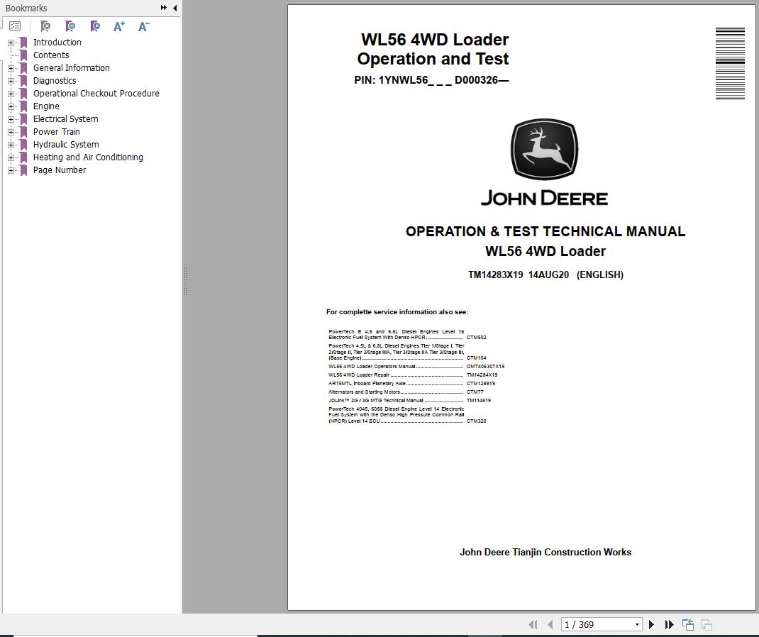

John Deere WL56 4WD Operation Test Technical Manual TM14283X19


Support Contact:
Admin@autoepcsoft.org
John Deere WL56 4WD Operation Test Technical Manual TM14283X19
Data Size: 37.33 MB
File Type: PDF
Language: English
Manufacturer: John Deere
Applicable Machine: Loader
Document: Operation & Test Technical Manual
Machine Model: John Deere WL56 4WD Loader
PIN: 1YNWL56_ _ _ D000326—
Book Number: TM14283X19
Publication Date: 2020
Page: 369 Pages
List Contents:
General Information
Safety
Recognize Safety Information
Follow Safety Instructions
Operate Only If Qualified
Wear Protective Equipment
Avoid Unauthorized Machine Modifications
Add Cab Guarding for Special Uses
Inspect Machine
Stay Clear of Moving Parts
Avoid High-Pressure Fluids
Avoid High-Pressure Oils
Work In Ventilated Area
Prevent Fires
Clean Debris from Machine
Prevent Battery Explosions
Handle Chemical Products Safely
Dispose of Waste Properly
Prepare for Emergencies
Use Steps and Handholds Correctly
Start Only From Operator′s Seat
Use and Maintain Seat Belt
Prevent Unintended Machine Movement
Avoid Work Site Hazards
Use Special Care When Operating Loader
Keep Riders Off Machine
Avoid Backover Accidents
Avoid Machine Tip Over
Operating on Slopes
Operating or Traveling On Public Roads
Inspect and Maintain ROPS
Add and Operate Attachments Safely
Park and Prepare for Service Safely
Service Cooling System Safely
Service Tires Safely
Remove Paint Before Welding or Heating
Make Welding Repairs Safely
Drive Metal Pins Safely
Diagnostics
Engine Control Unit (ECU) Diagnostic Trouble Codes
Engine Control Unit (ECU) Diagnostic Trouble Codes
91.03— Primary Analog Throttle Out of Range High
91.04— Engine Throttle Open or Short
97.03— Water-in-Fuel Signal Out of Range High
97.04— Water-in-Fuel Signal Out of Range Low
97.16— Water-in-Fuel Detected
110.00— Coolant Temperature Signal Extremely High
110.03— Coolant Temperature Signal Out of Range High
110.04— Coolant Temperature Signal Out of Range Low
110.15— Coolant Temperature Signal Slightly High
110.16— Coolant Temperature Signal Moderately High
Operational Checkout Procedure
Operational Checkout Procedure
Operational Checkout
Engine
Theory of Operation
John Deere Engine
Cold Start Aid System Theory of Operation—If Equipped
System Diagrams
Engine Fuel System Component Location
Engine Cooling System Component Location
Engine Intake and Exhaust Component Location
Diesel Fired Coolant Heater (A8) Component Location—If Equipped
Diagnostic Information
John Deere Engine
Engine Cranks/Will Not Start
Engine Misfires-Runs Irregularly
Engine Does Not Develop Full Power
Engine Emits Excessive White Exhaust Smoke
Engine Emits Excessive Black or Gray Exhaust Smoke
Engine Will Not Crank
Engine Idles Poorly
Abnormal Engine Noise
Excessive Fuel Consumption
Fuel in Oil
Low Pressure Fuel System Check
Adjustments
John Deere Engine
Tests
John Deere Engine
Electrical System
Theory of Operation
Start and Charge Circuits Theory of Operation
Controller Area Network (CAN) Circuits Theory of Operation
Engine Control Unit (ECU) Circuits Theory of Operation
Display Unit Circuits Theory of Operation
Transmission Control Unit (TCU) Circuits Theory of Operation
Park Brake Circuit Theory of Operation
JDLink™ Circuit Theory of Operation—IF Equipped
System Diagrams
Electrical Diagram Information
Electrical Schematic Symbols
System Functional Schematic, Wiring Diagram, and Component Location Master Legend
System Functional Schematic
Power and Ground Cables (W1) Component Location
Loader Frame Harness (W2) Component Location
Loader Frame Harness (W2) Wiring Diagram
Load Center Harness (W3) Component Location
Load Center Harness (W3) Wiring Diagram
Engine Harness (W6) Component Location
Engine Harness (W6) Wiring Diagram
Beacon Light Harness (W8) Component Location—If Equipped
Beacon Light Harness (W8) Wiring Diagram—If Equipped
Rear Frame Harness (W13) Component Location
Rear Frame Harness (W13) Wiring Diagram
License Plate Light Harness (W14) Component Location—If Equipped
License Plate Light Harness (W14) Wiring Diagram—If Equipped
Cab Roof Harness (W19) Component Location
Cab Roof Harness (W19) Wiring Diagram
Heater and Air Conditioner Harness (W20) Component Location
Heater and Air Conditioner Harness (W20) Wiring Diagram
Radio Harness (W23) Component Location—If Equipped
Radio Harness (W23) Wiring Diagram—If Equipped
Fuel Injector Harness (W32) Component Location
Fuel Injector Harness (W32) Wiring Diagram
Auxiliary Fuel Filter Harness (W33) Component Location—If Equipped
Auxiliary Fuel Filter Harness (W33) Wiring Diagram—If Equipped
Diesel Fired Coolant Heater Harness (W34) Component Location—If Equipped
Diesel Fired Coolant Heater Harness (W34) Wiring Diagram—If Equipped
JDLink™ Harness (W36) Component Loaction—If Equipped
JDLink™ Harness (W36) Wiring Diagram—If Equipped
Fuse and Relay Specifications
Diagnostic Information
Service ADVISOR™ Diagnostic Application
Service ADVISOR™ Connection Procedure
Reading Diagnostic Trouble Codes with Service ADVISOR™ Diagnostic Application
Intermittent Diagnostic Trouble Code (DTC) Diagnostics
Diagnostic Trouble Codes—After Machine Repair
Electrical Component Specifications
Adjustments
Boom Height Kickout (BHKO) Adjustment
Return-to-Dig Adjustment
Tests
Alternator Test
Transmission Control Valve Solenoid Check
Clutch Cut-Off Sensor Check
Connector Terminal Test
Power Train
Theory of Operation
TeamMate™ IV Axles
Power Train Operation
Torque Converter Operation
Transmission Operation
Transmission Operation—First Gear Forward
Transmission Clutch Pack Engagement and Solenoids Activated
Clutch Pack Operation
Transmission Hydraulic System
Transmission Control Valve Component Operation
Transmission Clutch Modulation Operation
Thermal Bypass Valve Operation
Axle Oscillation
Inboard Planetary Axle Operation
Differential Operation
Final Drive—Axle Operation
Service Brake Operation
Park Brake Operation
System Diagrams
Transmission System Schematic—First Forward
Power Train Component Location
Transmission Component Location
Diagnostic Information
Transmission Clutch Slippage
Machine Will Not Move in Either Direction
Machine Will Not Shift Correctly
Transmission System Pressure Is Low in Neutral
Transmission Pressure Is Low (One or Two Gear Ranges)
Transmission Shifts Too Slow
Transmission Shifts Too Fast
Machine Creeps in Neutral
Transmission Hydraulic System Overheats
Transmission Excessive Noise
Oil Aerated
Oil Ejected from Filler Tube
Machine Vibrates
Machine Power and Acceleration Low
Torque Converter Stall RPM
Differential Oil Level Rises
Differential Oil Level Low
Differential and Axle Noise Excessive
Axle Overheats
Service Brakes Poor or Do Not Apply
Service Brakes Aggressive
Service Brakes Dragging
Service Brakes Lock Up
Service Brakes Chatter
Service Brake Warning Light On
Driveline Excessive Vibration or Noise
Park Brake Will Not Hold
Park Brake Will Not Release
Park Brake Overheats
Park Brake Light Does Not Come On
Park Brake Will Not Apply
Adjustments
Service Brake Bleeding Procedure
External Service Brake Inspection
Service Brake Accumulator
Transmission Sensor Adjustment
Park Brake Adjustment
Tests
Transmission Oil Warm-Up Procedure
Park Brake Pressure Test
Park Brake Drag Test
Transmission Pump Flow Test
Transmission System Pressure Test
Transmission Clutch Pressure Test
Transmission Element Leakage Test
Transmission Lube Pressure Test
Torque Converter-In Pressure Test
Torque Converter-Out Pressure Test
Torque Converter Relief Pressure Test
Torque Converter—Out Flow Test
Torque Converter Stall Speed Test
Transmission Oil Cooler Thermal Bypass Valve Temperature Test
Transmission Oil Cooler Thermal Bypass Valve Pressure Test
Transmission Oil Cooler Restriction Test
Axle Breather Test
Hydraulic System
Theory of Operation
Loader Hydraulic System Operation
Loader Hydraulic Pump Operation
Hydraulic Pump Manifold Operation
Steering System Component Operation
Steering Valve Operation
Pilot Pressure Reducing Valve Operation
Service Brake Hydraulic System Operation
Service Brake Accumulators Operation
Service Brake Valve Operation
Pilot Control Lever Operation
Loader Control Valve Operation
Loader Control Valve with Auxiliary Function Operation—If Equipped
Boom Section Operation-Boom Down and Steering
Bucket Section Operation
Auxiliary Section Operation—If Equipped
Main Relief Valve Operation
Circuit Relief With Anticavitation Valve Operation
Anticavitation Valve Operation
Hydraulic Return Filter Operation
System Diagrams
Hydraulic System Schematic
Steering Circuit Component Location
Loader Circuit Component Location
Loader Circuit with Auxiliary Function Component Location—If Equipped
Service Brake and Park Brake Component Location
Hydraulic Pump Manifold (Hydraulic System Component Location)
Diagnostic Information
No Hydraulic Functions
Hydraulic Functions Slow
Loader Hydraulic Pump Noisy
Loader/Steering Hydraulic Pump Noisy
No Steering Function
Boom Float Function Not Working
One Hydraulic Function Not Working
Hydraulic Function Drifts Down
Boom Down Does Not Work (Engine Off)
Oil Overheats
Hydraulic Oil Foams
Constant Steering Required to Maintain Straight Travel
Slow Steering Wheel Movement Will Not Cause Frame Movement
Steering Wheel Turns Without Resistance and Causes No Frame Movement
Steering Erratic
Steering Wheel Free Play
Orbital Steering Valve Binds or Locks Up
Steering Wheel Turns By Itself
Machine Turns in Opposite Direction as Steering Wheel
Steering Wheel Kickback
Steering Jerky
Adjustments
Pilot Control Lever Adjustment
Accumulator Precharge
Tests
Hydraulic Oil Sampling Procedure
Hydraulic Oil Warm-Up Procedure
Vacuum Pump Installation
Hydraulic System Pressure and Accumulators Discharge
JT02156A Digital Pressure and Temperature Analyzer Kit Installation
Steering/Loader Hydraulic Pump Flow Test
Loader Hydraulic Pump Flow Test
Main Relief Valve Pressure Test
Circuit Relief with Anticavitation Valve Pressure Test
Loader Cylinder Drift Test
Boom, Bucket, and Steering Cylinder Leakage Test
Hydraulic Oil Cooler Restriction Test
Orbital Steering Valve Leakage Test
Steering Cylinder Drift Test
Pilot Control Valve Pressure Test
Pilot Pressure Reducing Valve Pressure Test
Cycle Time Test
Service Brake Accumulator Gas Precharge and Low Brake Pressure Warning Test
Service Brake Valve Pressure Test
Service Brake Valve Leakage Test
Hydraulic Oil Filter Inspection Procedure
Heating and Air Conditioning
Theory of Operation
Air Conditioning System Cycle of Operation
System Diagrams
Air Conditioner and Heater Component Location
Diagnostic Information
Air Conditioning System Does Not Operate
Air Conditioner Does Not Cool Interior of Cab
Air Conditioning Runs Constantly, Too Cold
Heater System Does Not Operate
Heater Does Not Warm Interior of Cab
Interior Windows Continue to Fog
Tests
Refrigerant Cautions and Proper Handling
R134a Refrigerant Cautions
R134a Oil Charge Capacity
R134a Refrigerant Charge Capacity
Refrigerant Hoses and Tubing Inspection
R134a Air Conditioning System Test
Operating Pressure Diagnostic Chart
Air Conditioning High/Low Pressure Switch Test
Freeze Control Switch Test
Refrigerant Leak Testing
Page Number