
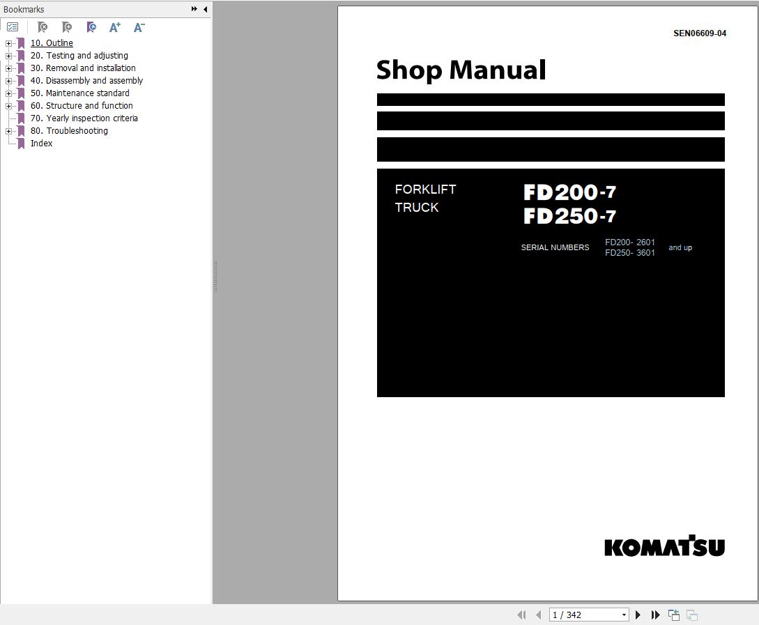
Komatsu FD200-7 FD250-7 Shop Manual SEN06609-04 2026


Support Contact:
Admin@autoepcsoft.org
Komatsu FD200-7 FD250-7 Shop Manual SEN06609-04 2026
Data Size: 18.28 MB
File Type: PDF
Language: English
Manufacturer: Komatsu
Applicable Machine: Forklift
Document: Shop Manual, Electric and Hydraulic Diagrams
Machine Model: Komatsu FD200-7 FD250-7 Forklift
Serial Number:
FD200- 2601 and up
FD250- 3601 and up
Book Number: SEN06609-04
Publication Date: 2026
Page: 342 Pages
List Contents:
10. Outline
Specifications
Safety items for maintenances
Standard tightening torque table
How to use Loctite
20. Testing and adjusting
Service data
Replace fuel filter
TORQFLOW transmission case
Drive axle and brake
Adjust accelerator pedal
Adjust parking brake
Measure lift and tilt cylinder drift (Lift truck with fork specification)
Lubrication points
Cooling system
Check and replace alternator belt
Check and replace auto-tensioner
Hydraulic tank
Adjust mast
Air bleeding procedure
Specified fuels and lubricants
Lamp display of KOMTRAX terminal
Brake accumulator
Work equipment accumulator
30. Removal and installation
Weight table
Remove and install units
Engine
Torque converter and transmission
Mast
Lift cylinder
Removal and installation of KOMTRAX terminal
Battery
Wheel
40. Disassembly and assembly
Torque converter
TORQFLOW transmission
Transmission control valve
Drive axle and brake
Brake valve
Steering axle
Parking brake
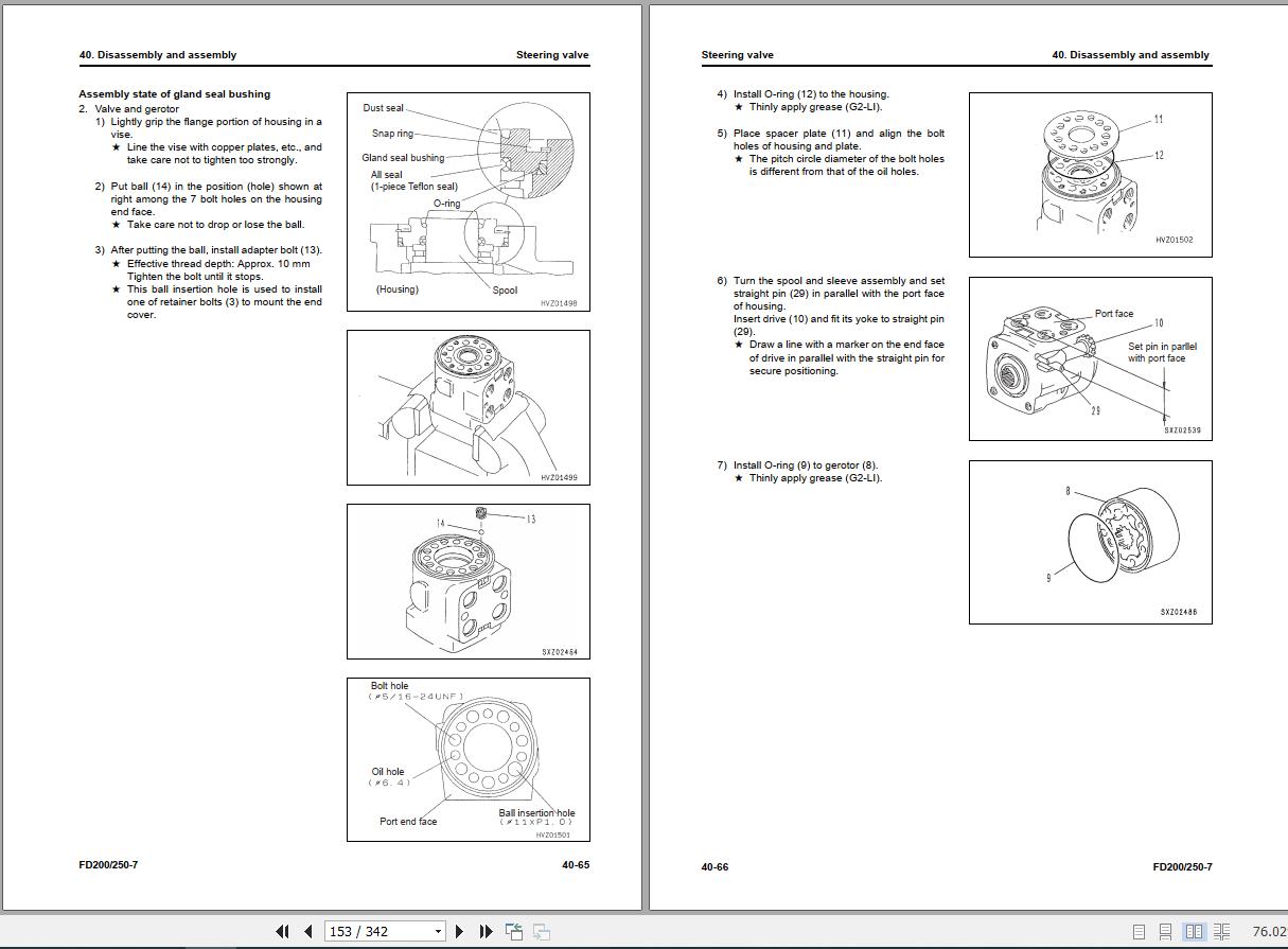
Steering valve
Hydraulic pump
Work equipment control valve
Mast
Lift cylinder
Tilt cylinder
Power steering cylinder
Side shift cylinder
Disassemble lift cylinder and tilt cylinder
50. Maintenance standard
Torque converter
TORQFLOW transmission
Transmission control valve
Differential
Disc brake
Steering axle
Power steering cylinder
Brake valve
Work equipment control valve
Lift cylinder
Tilt cylinder
Mast, fork carriage, and fork
60. Structure and function
Torque converter
TORQFLOW transmission
Automatic transmission
Drive axle and brake
Steering system
Steering axle
Work equipment
Meter panel
Electric circuit diagram (1/2)
Electric circuit diagram (2/2)
Hydraulic circuit diagram
70. Yearly inspection criteria
80. Troubleshooting
Check functions of troubleshooting tools and failure codes
Failure codes table
Electrical-system failure code record display function (only for interlock controller system)
Troubleshooting by failure code (only for interlock controller system)
Checking water pump for water leakage