Link Belt 750X4 Service Manual WLSM7007-00LX
Size: 171.33 MB
Language: English
Machine: Excavator
Machine Model: 750X4
Part Number: WLSM7007-00LX
Publication Date: Dec. 2016
Pages: 2004 Pages
The Bookmarks of Link Belt 750X4 Excavator Service Manual WLSM7007-00LX Dec. 2016:
Excavator
SAFETY
Safety, general information and standard torque data
General Information
Standard Torque Data For Cap Screws And Nuts
A. LOWER
Main Equipment Table
Main Equipment Structure and Operation Explanation
Port Diagram
Basic Functions
Removal and Installation of Track
Removal and Installation of Shoe Assembly
Removal and Installation of Shoe Plate
Removal and Installation of Roller
Removal and Installation of Upper Roller
Assembly and Disassembly of Upper Roller
Removal and Installation of Lower Roller
Assembly and Disassembly of Lower Roller
Removal and Installation of Retractable Lower Frame
Removal and Installation of Drive Sprocket
Removal and Installation of Take-up Roller
Assembly and Disassembly of Take-up Roller
Removal and Installation of Grease Cylinder
Assembly and Disassembly of Grease Cylinder
Removal and Installation of Center Joint
Disassembly and Assembly of Center Joint
Removal and Installation of Travel Motor
Assembly and Disassembly of Travel Motor
Maintenance Standards
Pressure Measurement and Adjustment Procedures
Drain Volume Measurement Procedures
Air Bleed Procedure
B. C. SWING UNIT, COUNTERWEIGHT
Main Equipment Table
Counterweight Removal System (Option)
Main Equipment Structure and Operation Explanation
Port Diagram
Basic Functions
Removal and Installation of Swing Unit
Assembly and Disassembly of Swing Unit
Assembly and Disassembly of Swing Motor
Removal and Installation of Counterweight
Removal and Installation of Counterweight Removal System
Pressure Measurement and Adjustment Procedures
Drain Volume Measurement Procedures
Air Bleed Procedure
H. ENGINE
Main Equipment Table
Basic Functions
Main Data
Function, Structure, Operation
Function, Structure, and Operation of Emission Control
SCR Control System Inspection
Operation Explanation of SCR
Diagnosis for Each Symptom
Symptom
Functional Inspection
Removal and Installation of Engine Assembly
Removal and Installation of Fuel Cooler, Engine Intercooler, Radiator, and Oil Cooler
Removal and Installation of Turbo Charger
Removal and Installation of EGR Valve
Removal and Installation of EGR Cooler
Removal and Installation of Engine Hood
Removal and Installation of SCR
Removal and installation of Silicon Controlled Rectifier Catalyst
Removal and Installation of Cylinder Head Cover
Removal and Installation of Cylinder Block
Lubrication System
Cooling System
Induction System
Exhaust System
Aux. Emission Control Devices System
Removal and Installation of Fuel Tank
Removal and Installation of Urea Pump
Removal and Installation of Urea Solution Tank
Removal and Installation of Fuel Supply Pump
Removal and Installation of Common Rail Assembly
Removal and Installation of Injector
Removal and installation of Idle Gear
Removal and installation of Crankshaft
Removal and installation of Piston
Removal and installation of Camshaft
Removal and installation of Flywheel
Removal and Installation of Flywheel housing
Removal and Installation of Timing Gear Case
Removal and installation of Rocker Arm Shaft
Removal and installation of Intake Throttle Valve
Removal and Installation of Starter Motor
Removal and Installation of Alternator
Removal and Installation of Glow Plug
Removal and installation of Fuel Filter
Removal and installation of Relief Valve
Removal and installation of Fuel Filter Element
Removal and installation of Fuel temperature sensor
Removal and installation of Pressure limiter
Removal and installation of Fuel pressure sensor
Removal and Installation of Fuel filter pressure
Removal and Installation of Engine coolant temperature sensor
Removal and Installation of CKP sensor
Removal and Installation of CMP sensor
Removal and Installation of Oil Pressure Sensor
Removal and installation of Pressure Sensor/Boost Temperature Sensor
Removal and Installation of IMT sensor
Removal and installation of MAF and IAT sensor
Removal and installation of Charge Air Cooler Temperature Sensor 1
Sampling Procedure
Removal and Installation of Exhaust gas temperature sensor
Removal and installation of EGR Gas Temperature Sensor 1
Removal and installation of EGR Gas Temperature Sensor 2
Removal and installation of EGR Gas Temperature Sensor 3
Removal and installation of EGR Gas Temperature Sensor 4
Removal and installation of NOx Sensor
Removal and Installation of Exhaust gas temperature sensor 3
Removal and installation of DEF Sensor
Engine-related Diagnostic Trouble Code List
Engine-side Trouble
J. HYDRAULIC EQUIPMENT (PUMP, OPERATION SYSTEM VALVE)
Main Equipment Table
Basic Functions
Port Diagram
Hydraulic Pump
Hydraulically-operated fan pump
Hydraulically-operated fan motor
Control Valve
5 Stack Solenoid Valve Operation Explanation
Upper Pilot Valve (remote control valve)
Travel Pilot Valve (remote control valve)
Cushion Valve
Selector Valve (2-way)
Removal and Installation of Hydraulic Reservoir
Removal and Installation of Hydraulic Pump
Removal and Installation of Pump Coupling
Removal and Installation of Control Valve
Removal and Installation of Travel Remote Control Valve
Removal and Installation of Operation Remote Control Valve
Removal and Installation of 5 Stack Solenoid Valve
Removal and Installation of Cushion Valve
Removal and Installation of Hydraulically-Operated Fan Pump
Removal and Installation of Hydraulically-Operated Fan Motor
Procedures for Assembly and Disassembly of Hydraulic Pump Main Unit
Pump Main Unit Maintenance Standards
Regulator Maintenance Standards
Assembly and Disassembly of Control Valve
Assembly and Disassembly of Control Valve
Procedures for Assembly and Disassembly of Operation Remote Control Valve
Procedures for Assembly and Disassembly of Travel Remote Control Valve
Assembly and Disassembly of Cushion Valve
Pressure Measurement and Adjustment Procedures
Hydraulic Pump Flow Measurement Procedures
Air Bleed Procedure
Sampling Procedure
Hydraulic Equipment Layout
Overall View
N. CAB
Removal and Installation of Operator's Seat
Removal and Installation of Cab Assembly
Removal and Installation of Wiper
Removal and Installation of Cab Front Glass
Window Lock Adjustment Procedures
Removal and Installation of Housing Guardrail
Tightening Torque
R. ELECTRICAL PARTS
Basic Functions
Service Support
Connection Connector Pin Layout
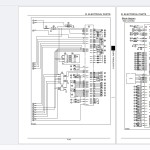
Sequence Circuit Diagram
Electrical Equipment Layout Diagram
Removal and Installation of Wiper Controller
Removal and Installation of Wiper Motor
Removal and Installation of ECM
Removal and Installation of Main Controller
Removal and Installation of DCU
Removal and Installation of Monitor
Removal and Installation of Rear View Camera
Removal and Installation of Side Camera (Right)
Removal and Installation of Side Camera (Left)
Removal and Installation of WAVES Controller
How to set WAVES
Air Conditioner Overall Diagram
Assembly and Disassembly of Unit
Removal and Installation of Compressor
Removal and Installation of Condenser
Removal and Installation of Receiver Dryer
Work Precautions
V. ATTACHMENTS
Main Equipment Table
Maintenance Standards
Removal and Installation of Bucket Cylinder
Removal and Installation of Arm Cylinder
Removal and Installation of Boom Cylinder
Procedures for Operation/Assembly and Disassembly of Hydraulic Cylinder
Port Diagram
Air Bleed Procedure
Removal and Installation of HBCV
Removal and Installation of Arm HBCV
Removal and Installation of Boom HBCV
Removal and Installation of Bucket
Removal and Installation of Bucket Link
Removal and Installation of Arm
Removal and Installation of Boom
Z. OTHER
Changes from Model -5
Specifications (750X4)
Specifications (750X4) (Large Soil Volume)
Arm Dimension
Main Unit Weight
Bolt Size and Torque Table
Overall View
WORK RANGE DIAGRAM
FLUIDS AND LUBRICANTS
Main-unit-related Diagnostic Trouble Code List
Main Unit-side Trouble
List of special tools
Abbreviation
Disassembly and Assembly


