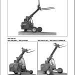
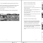
Manitou TMT 315 315-3 320-3 SIFL 320 FL TURBO HT 25-20C 25-20SR 25-15CR S1 E2 Service Manual 547517
Size: 185 MB
Language: English French
Machine: Forklift
Machine Model:
TMT 322, TMT 325, TMT 320 SI, TMT 320 SIFL, TMT 315 SIFL
TMT 320-3 TMT 320-3FL, TMT 320-3SI, TMT 320-3SIFL, TMT 315-3SIFL
TMT 320, TMT 320 FL HT, TMT 320 FL HT TURBO, TMT 320 FL
Part Number: 547517
List File:
Transmission Service Manual:
Repairing The Steering System On The Tmt With Three Driven Wheels 100-M24 EN 16 Pages 2001
Poclain Hydraulics 78 Pages FR
Characteristics Service Manual 0-1-M24 EN 52 Pages 2001
Rear Steering Pivot Assembly Service Manual 35-2-M67EN 8 Pages
Elements Of The Jib & Removal Of The Cylinder Service Manual 50-3-M67EN 18 Pages
Group 10 Engine Service Manual 547517 FR 96 Pages 1996
Group 70 Dismantling Association Service Manual 70-3-80-M24 FR 64 Pages 2000
Group 80 Electric Diagram Service Manual 80-6-M24 EN 36 Pages 2001
Group 90 Electrical & Hydraulic Service Manual 547517 FR 6 Pages
The Bookmarks Of Manitou TMT 315 315-3 320-3 SIFL 320 FL TURBO HT 25-20C 25-20SR 25-15CR S1 E2 Forklift Service Manual:
Repairing The Steering System On The Tmt With Three Driven Wheels
Description Of The Movements Of The
Wheels In The Various Directional Modes
Steering Hydraulic Diagram
Steering Electric Diagram
Various Potential Breakdowns
Steering Electric Diagram
Various Potential Breakdowns
Electric Diagram Of Steering Box
Poclain Hydraulics
Characteristics
Engine
Cooling Circuit
Electric Circuit
Hydrostatic Transmission
Front Wheel Reducer
Rear Wheel Reducer
Brake
Front Tyres
Hydraulic Circuit
Rear Steering Pivot Assembly
Rear Steering Pivot Assembly
Removal Of The Rear Steering Pivot
Removal Of The Rear Steering Cylinder
Elements Of The Jib & Removal Of The Cylinder
Elements Of The Jib
Adjustment And Immobilization Of The Jib Wear Pads
Removal Of The Tilting Cylinder
Removal Of The Carriage
Removal Of The Telescoping Cylinder
Removal Of The Telescope
Removal Of The Translation Jib Cylinder
Group 10 Engine
Introduction
Engine Features
Safety Precautions
Section 1 General Information
Section 2 The Basic Engine
Section 3 The Lubricating Oil System
Section 4 The Cooling System LPA
Section 5 The Cooling System LPW and LPWS
Section 6 The Fuel System
Section 7 Industrial Electrical Wiring Diagrams
Section 11 The Engine Builds
Section 12 Dismantle and Rebuild
Section 13 Conversion Factors and Formulae
Index
Page Issue Record
Group 70 Dismantling Association
A Disassembly And Reassembly Of The Complete Rod
B Disassembly And Reassembly Of The Piston And The Closing Ring
C Disassembly And Reassembly Of The Piston Gaskets
D Disassembly And Reassembly Of Joints Of The Closing Ring
E Applying The Net Brake
F Cylinder Boards
Group 80 Electric Diagram
ELECTRIC DIAGRAM TMT 322 / TMT 325 / TMT 320 / TMT 320 FL /
TMT 320 FL / TMT 320 FL HT / TMT 320 FL TURBO HT / TMT 320 SI /
TMT 320 SIFL / TMT 315 SIFL
ELECTRIC DIAGRAM TMT 320-3SI / TMT 320-3SIFL / TMT 315-3SIFL
TMT 320-3 / TMT 320-3FL
ELECTRIC DIAGRAM TMT 320-3SI / TMT 320-3SIFL / TMT 315-3SIFL
TMT 320-3 / TMT 320-3FL
Optional Road Lights
Road Lighting Optional Elements
Schematic Diagram
Electrical Box Connection
Troubleshooting
Group 90 Electrical & Hydraulic
Operating Principle
Elements Of Kit
Location Of Component
Electrical Diagram
Hydraulic Diagram
Troubleshooting
?Contact Us: “Click Here”
?Payment Method: “Click Here”
?Shopping Guide: “Click Here”
?More Product: Manitou Operation, Parts & Repair Service Manual PDF ▶


