
Sany SY750H Hydraulic Excavator Service Manual Diagrams 2021


Support Contact:
Admin@autoepcsoft.org
Sany SY750H Hydraulic Excavator Service Manual Diagrams 2021
Data Size: 57.83 MB
File Type: PDF
Language: English
Manufacturer: Sany
Applicable Machine: Hydraulic Excavator
Document: Service Manual, Electrical Diagram, Hydraulic Diagram
Machine Model: Sany SY750H Excavator
Engine: Isuzu AH-6WG1
Publication Date: 2021
Page: 588 Pages
List Contents:
1 Preface
1.1 Reading Method of Service Manual
1.2 Explanation on Terms for Maintenance Standards
1.3 Handling of Electrical Component and Hydraulic Components
2 Safety
2.1 Instructions on Safety Signs
2.2 General Notices
2.3 Preparatory Work before Maintenance
2.4 Notices for Maintenance/Repair
2.5 Other Notices
3 Technical Specification
3.1 Specified size
3.2 Technical Specification
3.3 Table of Weight
3.4 Engine oil, fuel and coolant
3.5 Feature curve of engine
4 Structure, function and maintenance standard
4.1 Engine and Cooling System
4.2 Transmission Train
4.3 Lower travelling device
4.4 Hydraulic system (Part 1)
4.5 Hydraulic system, Part 2
4.6 Hydraulic system, Part 3
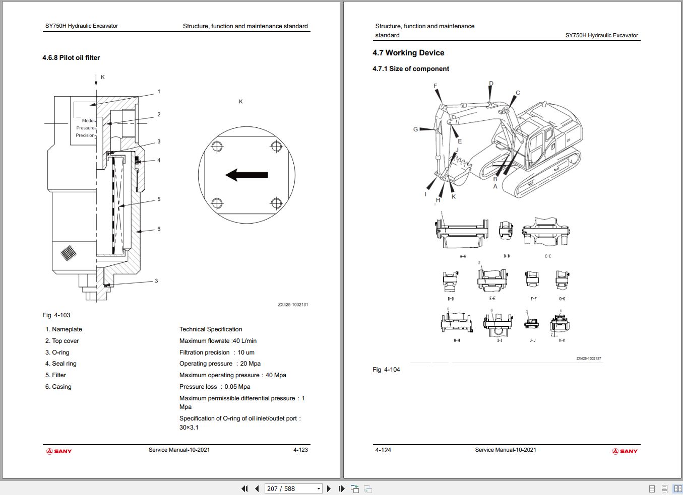
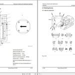
4.7 Working Device
4.8 Air conditioning system
4.9 Engine control
4.10 Electrical Control System
4.11 Display system
5 Standard value of components
5.1 Table of standard values for engine-related parts
5.2 Table for standard value of body-related parts
6 Testing and Adjustment
6.1 Measurement of Color of Exhaust Gas
6.2 Adjust the valve clearance
6.3 Measurement of compression pressure
6.4 Inspection and adjustment of injection timing
6.5 Measurement of engine oil pressure
6.6 Adjustment of engine speed sensor
6.7 Inspection and adjustment of A/C compressor belt tensioning device
6.8 Measurement of clearance of slewing support bearing
6.9 Inspection and adjustment of crawler plate tensioning device
6.10 Inspection and adjustment of hydraulic pressure in hydraulic oil ways for working device, slewing and travelling
6.11 Inspection and adjustment of control oil way pressure
6.12 Measurement of output pressure of electromagnetic valve
6.13 Measurement of output pressure of pilot valve
6.14 Adjustment of working device and slewing PPC valve
6.15 Inspection of hydraulic settlement of working device
6.16 Release of residual pressure in hydraulic oil way
6.17 Measurement of oil leakage
6.18 Air Bleeding for Every Device
6.19 Inspection on sensor
7 Trouble diagnosis and troubleshooting
7.1 Precautions during Trouble Diagnosis
7.2 Inspection before Trouble Diagnosis
7.3 Category and steps of trouble diagnosis
7.4 Connector
7.5 Trouble diagnosis when current trouble code is displayed
7.6 Trouble Diagnosis for Electrical System (Mode E)
7.7 Trouble diagnosis for hydraulic and mechanical systems (mode
8 Disassembling and Assembling
8.1 Notices for Operation
8.2 Dismantlement and installation of start motor assembly
8.3 Dismantlement and installation of fuel injection pump assembly
8.4 Dismantlement and installation of rear oil seal of engine
8.5 Dismantlement and installation of cylinder head assembly
8.6 Disassembling and assembling of cylinder head assembly
8.7 Dismantlement and installation of radiator assembly
8.8 Dismantlement and installation of engine and hydraulic pump assembly
8.9 Dismantlement and installation of final transmission assembly
8.10 Disassembling and assembling of final transmission assembly
8.11 Dismantlement and installation of slewing motor and slewing mechanism assembly
8.12 Disassembling and assembling of slewing motor and slewing mechanism assembly
8.13 Disassembling and assembling of guiding wheel assembly
8.14 Dismantlement and installation of sprocket
8.15 Dismantlement and installation of crawler assembly
8.16 Dismantlement and Installation of Back slewing Bearing Assembly
8.17 Dismantlement and installation of slewing table assembly
8.18 Dismantlement and installation of central slewing joint assembly
8.19 Disassembling and assembling of Central Back slewing Joint Assembly
8.20 Dismantlement and Installation of Hydraulic Oil Tank Assembly
8.21 Dismantlement and Installation of Control Valve Assembly
8.22 Dismantlement and installation of hydraulic pump assembly
8.23 Dismantlement and installation of oil seal in hydraulic pump input shaft
8.24 Dismantlement and installation of independent oil disperser
8.25 Disassembling and assembling of working device pilot valve assembly
8.26 Disassembling and assembling of travelling pilot valve assembly
8.27 Disassembling and assembling of hydraulic cylinder assembly
8.28 Dismantlement and Installation of Working Device Assembly
8.29 Dismantlement and installation of A/C device assembly
8.30 Dismantlement and installation of balance weight assembly
8.31 Dismantlement and installation of cab assembly
8.32 Dismantlement and installation of display screen
8.33 Dismantlement and installation of controller assembly
8.34 Dismantlement and installation of radio
8.35 Removal and Installation of Storage Battery
8.36 Dismantlement and installation of key switch
8.37 Dismantlement and installation of fuse box
8.38 Dismantlement and installation of wiper
8.39 Dismantlement and installation of relay
8.40 Installation and dismantlement methods for terminal of plug-in part
9 Hydraulic & Electrical Diagram
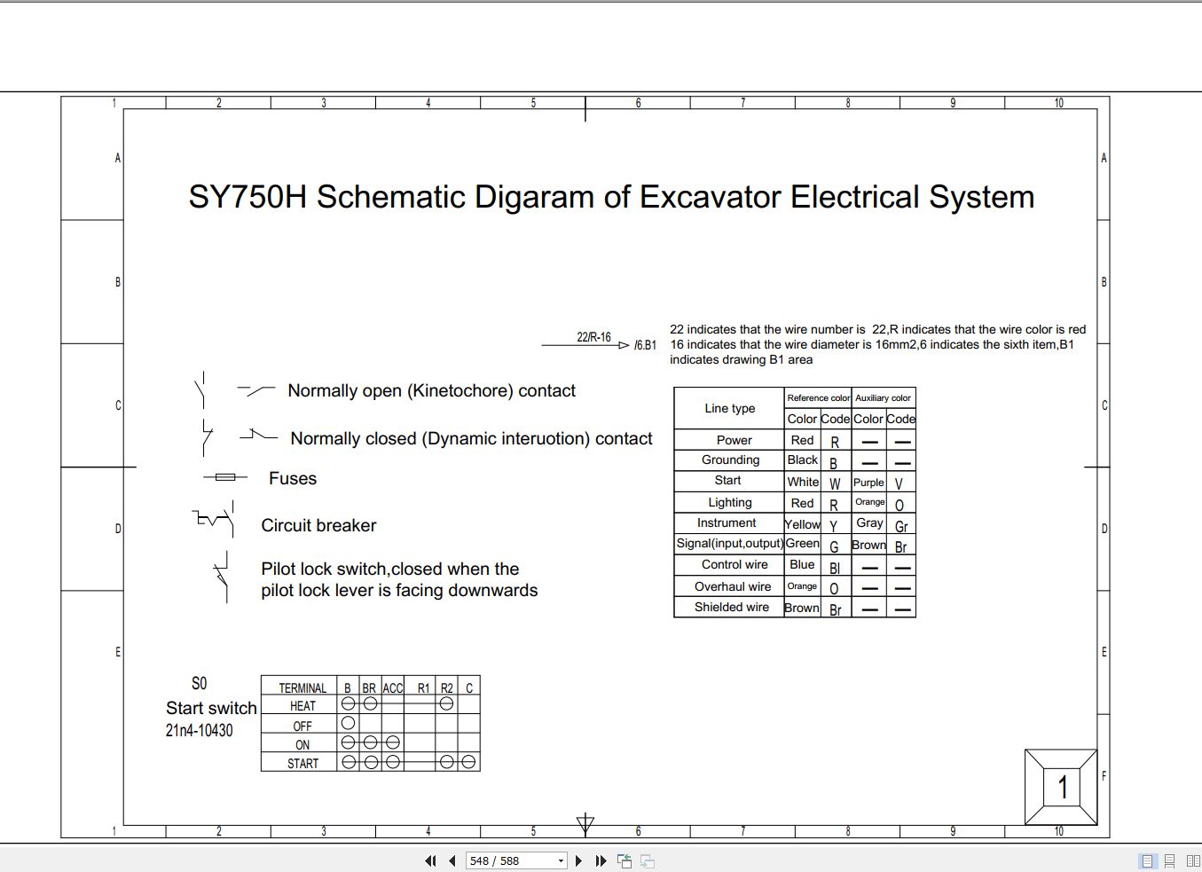
9.1 Symbol Description
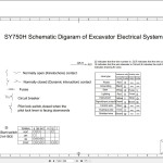
9.2 Start and Preheating Control
9.3 Assistant Function Control
9.4 CAN Communication
9.5 Assistant Function Control 2
9.6 Main Controller
9.7 Main Controller 2
9.8 Auxiliary Controller
9.9 Display
9.10 Engine Controller
9.11 AC Control
9.12 Fuse Box
9.13 Cab Harness
9.14 Control Switch Harness
9.15 Tool Box Harness
9.16 Pump Chamber Harness
9.17 Vehicle Body Harness
9.18 Body harness
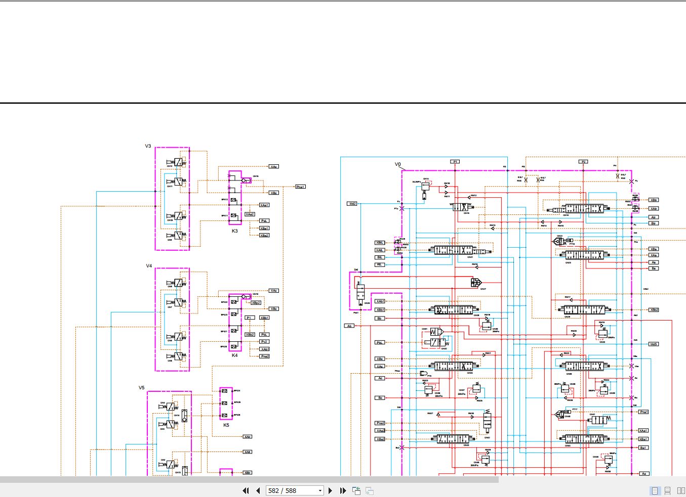
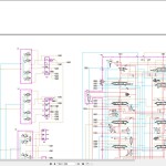
9.19 Hydraulic Schematic Diagram