
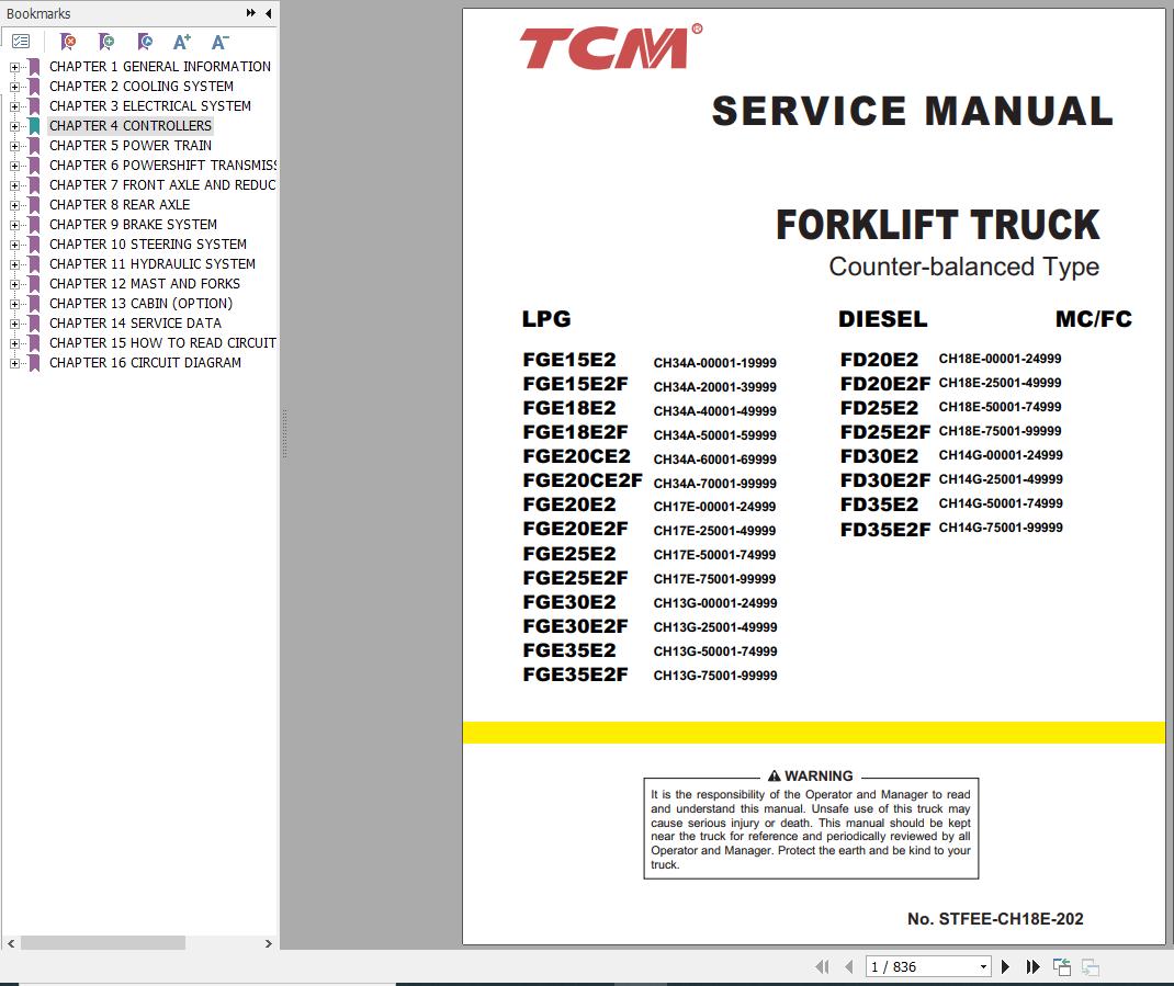
TCM FGE15E2 to FD35E2F Service Manual STFEE-CH18E-202


Support Contact:
Admin@autoepcsoft.org
TCM FGE15E2 to FD35E2F Service Manual STFEE-CH18E-202
Data Size: 51.21 MB
File Type: PDF
Language: English
Manufacturer: TCM
Applicable Machine: Forklift
Document: Service Manual, Electric and Hydraulic Diagrams
Machine Model: TCM FGE15E2, FGE15E2F, FGE18E2, FGE18E2F, FGE20CE2, FGE20CE2F, FGE20E2, FGE20E2F, FGE25E2, FGE25E2F,
FGE35E2, FGE35E2F, FD20E2, FD20E2F, FD25E2, FD25E2F, FD30E2, FD30E2F, FD35E2, FD35E2F, FGE30E2, FGE30E2F
Book Number: STFEE-CH18E-202
Publication Date: 2021
Page: 836 Pages
List Contents:
CHAPTER 1 GENERAL INFORMATION
1.1 Model View
1.2 Truck Models Covered
1.3 Serial Number Locations
1.4 Dimensions
1.5 Technical Data
1.6 Performance
CHAPTER 2 COOLING SYSTEM
2.1 Specifications
2.2 Fan Belt
2.3 Inspection and Adjustment
CHAPTER 3 ELECTRICAL SYSTEM
3.1 Chassis Electrical Components and Wiring Outline
3.2 Console Box
3.3 Main Electrical Components
3.4 Battery Maintenance
3.5 Meter Panel
3.6 Wire Color
3.7 Troubleshooting
CHAPTER 4 CONTROLLERS
4.1 Outline
4.2 Main Functions
4.3 Mast Interlock System
4.4 Driving Interlock System
4.5 Seat Belt Warning Icon
4.6 Parking Brake Warning Buzzer and Icon
4.7 Harness Codes
4.8 Truck Status Display and Troubleshooting
CHAPTER 5 POWER TRAIN
5.1 Removal and Installation (MC Models)
5.2 Removal and Installation (FC Models)
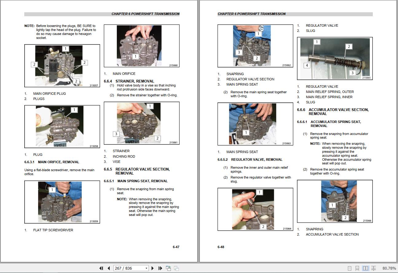
CHAPTER 6 POWERSHIFT TRANSMISSION
6.1 Structure and Functions
6.2 Removal and Installation
6.3 Outline
6.4 Powershift Transmission, Disassembly
6.5 Powershift Transmission, Assembly
6.6 Control Valve, Disassembly
6.7 Control Valve, Assembly
6.8 Inspection and Adjustment
6.9 Troubleshooting
6.10 Service Data
CHAPTER 7 FRONT AXLE AND REDUCTION DIFFERENTIAL
7.1 Structure
7.2 Removal and Installation
7.3 Disassembly and Assembly
7.4 Troubleshooting
7.5 Service Data
CHAPTER 8 REAR AXLE
8.1 Structure and Functions
8.2 Removal and Installation
8.3 Disassembly and Assembly
CHAPTER 9 BRAKE SYSTEM
9.1 Brake System Structure
9.2 Disassembly and Assembly
9.3 Inspection and Adjustment
9.4 Troubleshooting
9.5 Service Data
CHAPTER 10 STEERING SYSTEM
10.1 Structure and Functions
10.2 Disassembly and Assembly
10.3 Steering Valve
10.4 Troubleshooting
10.5 Service Data
CHAPTER 11 HYDRAULIC SYSTEM
11.1 Structure and Functions
11.2 Disassembly and Reassembly
11.3 Inspection and Adjustment
11.4 Troubleshooting
11.5 Service Data
11.6 MC Control Valve
11.7 FC Control Valve
CHAPTER 12 MAST AND FORKS
12.1 Simplex Mast
12.2 Duplex Mast
12.3 Triplex Mast
CHAPTER 13 CABIN (OPTION)
13.1 Cabin Model Exterior
13.2 Cabin Model Labels
13.3 Cabin Model Switches and Controls
CHAPTER 14 SERVICE DATA
14.1 Maintenance Schedule
14.2 Maintenance Note
14.3 Tightening Torque for Standard Bolts and Nuts
14.4 Periodic Replacement Parts
14.5 Lubrication Instructions
14.6 Dimensions and Performance
14.7 Special Service Tools
CHAPTER 15 HOW TO READ CIRCUIT DIAGRAMS
15.1 Description of Circuit Diagrams
15.2 How to Read Circuit Diagrams
15.3 How to Read Connector Diagrams
15.4 Abbreviation
CHAPTER 16 CIRCUIT DIAGRAM
16.1 Circuit Diagram for D04EG Engine Model
16.2 Circuit Diagram for GK21 / 25E Engine Model