Volvo EW130C Excavator Service Repair Manual
Size: 66.84 MB
Format: PDF
Language: English
Machine: Excavator
Document: Service Repair Manual, Electrical Wiring Diagram, Hydraulic Diagram
Machine Model: EW130C
Pages: 4330 Pages
The Bookmarks of Volvo EW130C Excavator Service Repair Manual:
Diagrams
Component list for diagram 1. Power supply equipm.
Component list for diagram 2. Monitoring equipm.
Component list for diagram 3. Monitoring equipm.
Component list for diagram 4. Service light equipm.
Component list for diagram 5. Sundry equipment
Component list for diagram 6. Optional equipment
Component list for diagram 7. Cab equipment
Component list for diagram 8. Working light equipm.
Component list for diagram 9. Control equipment
Component list for diagram 10. Control equipment
Component list for diagram 11. Climate control equipment
ECU A3 – pins in connector
EDU A9 – pins in connection
Electric circuit diagrams – component lists and index
Electric circuit diagrams and component lists – explanation key
Electrical distribution box A2
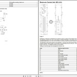
Electronic Central Unit, ECU (A3)
Electronic Display Unit, EDU (A9)
Fuse box A1 – main fuses F1–F15
Fuse box A1
Hydraulic diagram fig 1
Hydraulic diagram
Markings in hydraulic system
Parameter codes A9
Parameter codes, alarm codes and error codes – presentation on display
Parameter programming
Parameterkoder A3
Trip switches and sensors
Repair
AIR CONDITIONING
Alternator – replacement
Automatic adjusting of drum brakes (front- and rear wheel brakes)
Backlash in slewing system – measurement
Batteries – overhaul
Bucket cylinder – replacement
Cab – removal fitting
Cable marking
Centre passage (9)
Charging system – overhaul
Circuit relief and refilling valve, 3b – circuit relief function
Circuit relief and refilling valve
Component list for hydraulic circuit diagrams
Connection disconnection of vacuum pump – instructions
Control of gas pressure in brake accumulators for front and rear axle
Control pressure for the digging and slewing movements – checking and adjustment
Control pressure valve for dozer blade and left right outrigger
Control pressure valve for travel (12e) and brake (12f) plus the control valve (13i)
Control pressure valves (12a-b and 12c-d)
Control valve for digging brake
Control valve, cab heater – replacement
Counterweight – removal fitting
Description of hydraulic system
Description of machine
Description of moving functions in the hydraulic system
Description of slewing brake
Description of the brake system
Description of the steering system
Diesel engine – description
Dieseling in hydraulic cylinders
Digging equipment's hydraulic cylinders
Dipper arm – replacement
Dipper arm cylinder – replacement
Directional control valve (5b, -d, -f, -h, -k) in main valve block
Door catch – replacement
Electrical components – location
Electrical system – rules for work in the system
Electronic Central Unit, ECU (A3) – replacement
Electronic Display Unit, EDU (A9) – replacement
End position damping, dipper arm cylinder boom cylinder – adjustment
FIRE EXTINGUISHERS
Float position valve
Fuelling pump – replacement
Gas spring for window regulator – replacement
HAMMER AND GRAB EQUIPMENT
Hammer hydraulic option, installing new
Heater fan – replacement
Hose rupture valve – renovation
Hose rupture valve – replacement
Hose rupture valve (7c)
Hydraulic oil – recommendations
Hydraulic oil cooler
Hydraulic pressure – adjustment
Hydraulic pressure
Hydraulic quickfit – replacement of cylinder
Hydraulic quickfit
Hydraullic oil tank
Injection pump
Injector
Insert in control pressure valve – renovation
Interconnection valve (7
Jump-starting with a booster cable
Load-holding valve (8
Main dimensions
Main electrical units
Main valve block
Matarpump
MESH SCREEN, SUN ROOF
MESH SCREEN, WINDSCREEN
Nameplates and their location
P1 valve block (slewing valve block)
Pressure-limiting valve for servo pump
Pressure-limiting valves for P2 and P3
Pump gearbox, shaft seal – replacement
Pump P1 – replacement
Pumps P2 and P3 – replacement
Radial play in the digging equipment's pivot points – measurement
Recommendations for cleanliness during hydraulic work
Refill capacities
Rubber isolator for engine bracket – replacement
Servo (1d) and steering pump (1e)
Servo pump – replacement
Shimming of the digging equipment pivot points – Instructions
Shrinking – Instructions
Shunt (7t) and pressure back-up valve
Sink rate of digging equipment – measurement
Slewing brake – replacement
Slewing drift – measurement
Slewing motor – replacement
Slewing pressure-limiting valve
Slewing unit
SLOPE ROTATOR EQUIPMENT WITH EXISTING HAMMER AND GRAB EQUIPMENT
Solenoid and shuttle valves
Solenoid valves
Starter motor – replacement
SUN VISOR
Tightening torque
Transport data
Travel motor – replacement
Travel motor (4c)
Undercarriage – hydraulics
Upper windscreen – replacement
Valve slide in main valve block – replacement of spring
V-belt – replacement
Welding on the machine – instructions
Wheel steering valve
Window cassette in door – replacement
Window pane with moulding – replacement
Working pumps (1
Service Bulletins
Boom cylinder, improved connection
CareTrack Telematics system
CareTrack, new software version 2008w6
Changing glow plug in diesel engine heater from 24 V to 12 V with resistor unit
Check method on engine oil consumption 1
Check method on engine oil consumption
Checking cable between battery disconnector and starter motor
Crankcase ventilation, plastic foam sleeve replacement and cleaning in TD40GDE and TD40KEE type engines
Cylinder data
DEF AdBlue AUS32 sampling, method
Diesel fuels - quality and function 1
Diesel fuels - quality and function
ECU, functional check
Engine oil change, extended interval of 500 hours for low-emission engines
ENGINE RECONDITIONING
Fuel sampling, method
Hydraulic oil, environmental
Hydraulic pressure
Hydraulic system flushing method 1
Hydraulic system flushing method
Machine model
Modification of CareTrack wire harness
New product 1
New product
New TechTool VCADS Pro interface
Oil sampling, method
Oil sampling, sampling points
Rear crankshaft seal
Recommendations for Oil Sampling Intervals
Reporting of product misuse & near-miss report
Reports
Routines for reporting cracks on Boom and Arm
Serial no. on ÅKERMAN - VOLVO models from 1974 - up to 2001
Serial number location on machine components
Slewing ring clearance
Tightening torques
Torque for tightening hydraulic cylinder pistons
Vee belts
Volvo Product incident accident report & Interview Form
Special tool catalog
General
Index
Hooks
1. Enviroment and Safety equipment
2. Measuring equipment
3. Tightening and Loosening tools
4. Lifting equipment
5. Pullers and Pressing equipment
6. Drifts
7. Guide pins and Guide sleeves
8. Pliers
9. Fixtures
10. Tech Tool
11. Spare parts
Time Guide Current generation
Time Guide Old generation
Time Guide Previous generation


